Are you still verifying your PCB prototype visually?
With usability and functionality requirements increasing, PCB assemblies are becoming tighter. With space at a premium, some components are now being placed underneath other components. This brings increased challenges to designers to complete component placement before entering the routing process.
After completing component placement, it may take months for designer to complete the routing process and finish the entire PCB layout. At this point the CAM data can then be handed out to manufacturers for PCB manufacturing and assembly. After investing this much time and effort, you would probably expect the final prototype to be built as expected, with high quality and reliability.
Traditional way to verify your prototype
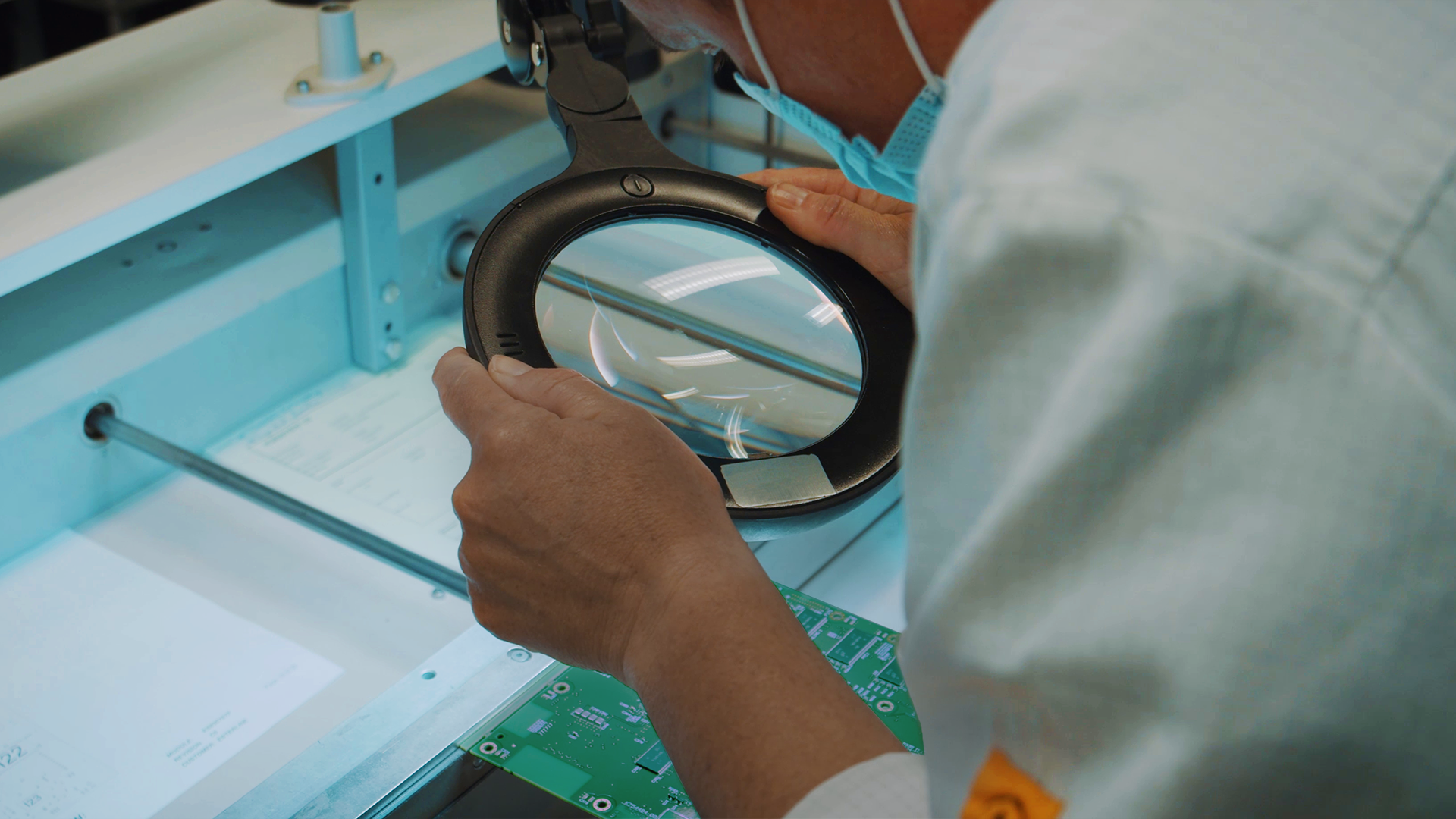
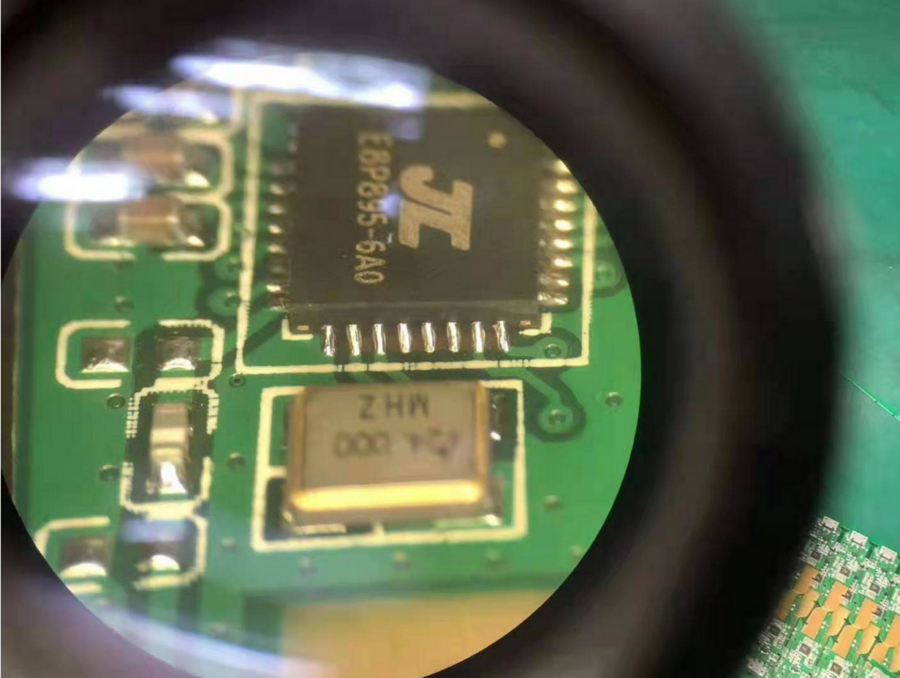
When the first prototype is manufactured, the NPI expert will inspect and verify the board visually under a magnifier. This is the traditional way to make sure the prototype is designed and manufactured and is in an overall good condition. Every land pattern and solder joint needs to be checked carefully under the magnifier, with higher magnification of 30x or 40x possibly needed for certain types of solder joint. For BTCs(Bottom Terminal Components), an X-Ray machine is used to verify the solder joint that is invisible from outside.
The visual inspection process can be used to verify a simple design with dozens of components, but when the design has a complexity of hundreds or even thousands of components, visually verification is becoming a time-consuming and unrealistic method.
3D prototype verification
Although visual verification is still popular today, another more efficient method is available to use for prototype verification. By making use of a digital twin, the same NPI expert can create a virtual 3D prototype and perform 3-D virtual verification digitally before the real product is manufactured.
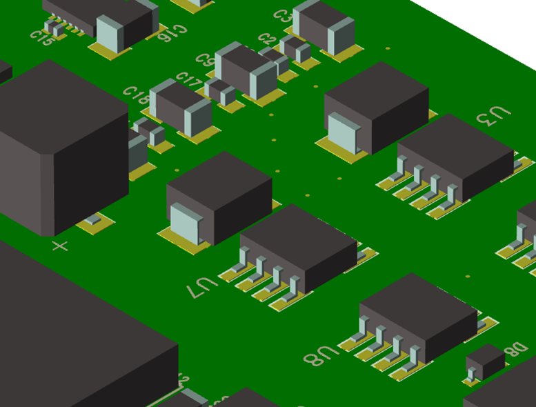
In 3D prototype verification, the 3D virtual prototype is created in a software system, designers and NPI experts can review and verify the prototype in the design stage before the real prototype is manufactured. In a digital 3D prototype, every component has its own 3D model with accurate component size and unique lead forms. Combining the PCB 3D model with the component 3D model brings together an accurate digital verification methodology.
Common prototype issues
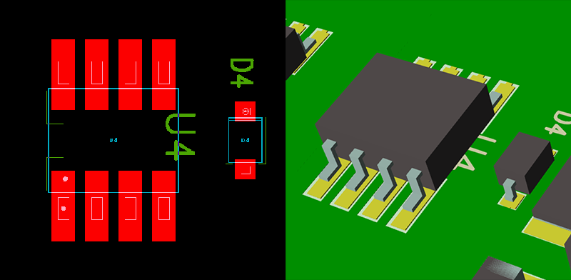
Here are some PCB fab and assembly issues that commonly arise in prototype verification. These issues are shown in traditional 2D view and 3D view separately.
- Reference designator is located under the component. The reference designator of U4 is located under its body, it is difficult to identify the component with improper placement of component reference designator.
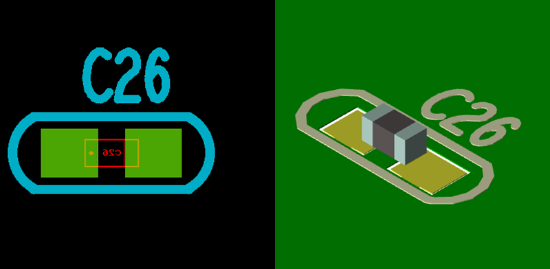
- Component mismatch with its land pattern. C26 is a 0603 discrete chip in the CAD data, but a 0402 component is used for this location in the BOM file, this is a mismatch issue between BOM and CAD file.
Challenges in 3D prototype verification
3D prototype verification is a good process for designers to review the prototype, but it also faces some challenges:
- Extensive 3D component libraries
Without extensive 3D component libraries, it is impossible to have a full visibility of 3D prototype.
- DFM capability awareness.
Currently 3D prototype capabilities are within PCB layout environment or mechanical design environments, but those tools do not provide knowledge of the DFM capability of your manufacturers.
These challenges existed for a long time until Valor NPI 2311 published its unique 3D viewer in November 2023.
Valor NPI 3D viewer
Valor NPI is the leading DFM software from Siemens DISW (Digital Industries Software), its manufacturing driven design solution have a full understanding on manufacturing capabilities, which helps thousands of OEM companies to prevent DFM issues in previous decades.
Starting from November 2023, Valor NPI also provides its unique 3D viewer capability to the industry, which fills in the blank of the extensive 3D libraries and competent DFM capabilities that are missing in current 3D solutions. The unique 3D viewer, along with Valor NPI’s inbuilt more than 1 billion 3D component libraries and its unprecedented DFM capability, brings your prototype verification to the next level.
Let’s start to experience the new prototype verification process with the exciting 3D viewer of Valor NPI.