What’s New in Valor NPI 2311

Introduction:
Each new Valor NPI release brings exciting features and improvements, and Valor NPI version 2311 is no different. One of the most prominent recent changes for release 2311 is the 3D board viewer. This allows users to toggle between the typical 2-D board view, and a 3-D board view. While less visually prominent, the addition of high-risk component detection is no less impactful among the overall improvements. The Valor Parts Library now associates individual components with a manufacturing risk value. This allows you to consider at-a-glance relative yield values based on component choices. Valor NPI version 2311 also facilitates the placement of XD components in a zigzag array.
These changes come in addition to incremental product improvements and software fixes. These represent a glimpse of a few of the most interesting enhancements introduced in this release.
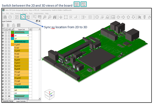
Review the Printed Circuit Board in 3-Dimensions.
The adoption of 3D views in the final validation stage of Printed Circuit Board (PCB) design introduces a realm of advantages that significantly elevate the precision and efficacy of the validation process.
As engineers strive for utmost accuracy, manufacturability and reliability in their designs, the three-dimensional representation provides a comprehensive and intuitive assessment of the PCB’s physical layout.
Potential manufacturing issues such as component shadowing the lead of a neighboring component are much easier to envision in a 3-dimensional illustration of the board, where the component height is clearly visible.
The Valor NPI version 2311 MRA 3D view provides real-life simulation of the PCB with all the required layer details and features and with exact geometry of VPL components and leads.
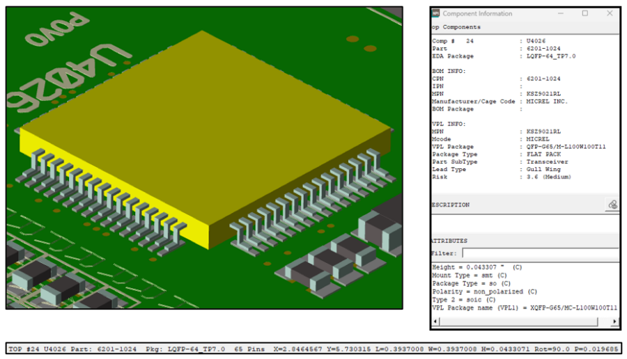
Detect High-Risk Components in your design.
Understanding whether your printed circuit board (PCB) design incorporates components with high solderability risk is important for ensuring the integrity and reliability of the board. Solderability issues can compromise the functionality of solder joints, potentially leading to electrical failures and reduced product lifespan. Identifying components with elevated solderability risk early in the design process allows for targeted interventions, such as adjusting pad designs or selecting alternative components, ensuring a smoother manufacturing process, minimizing defects, and ultimately delivering electronic products that meet high-quality standards.
In the Valor Parts Library (VPL) each package receives a risk score, which is based on its physical characteristic.
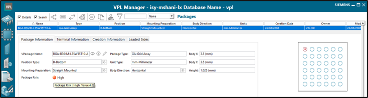
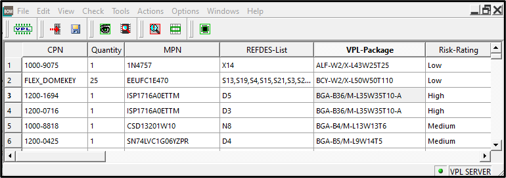
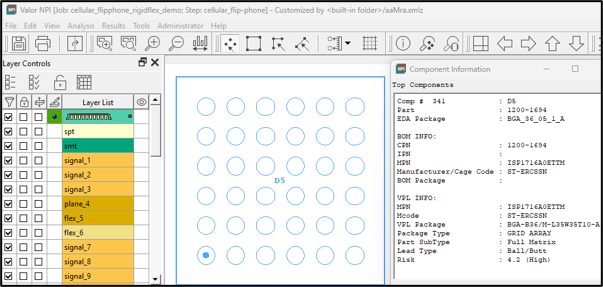
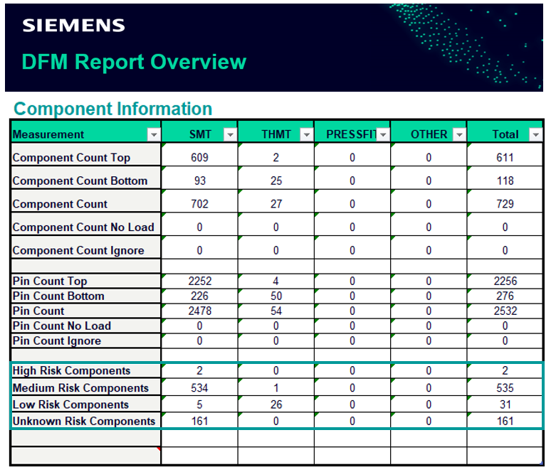
Valor NPI version 2311 brings this data into the actual board, with the ability to display the risk rate and score in the BOM and in each individual component information dialog, extract risk statistics in the MRA report and most importantly detect components with high-risk early in the design process.
BOM review
Component Information
ADM
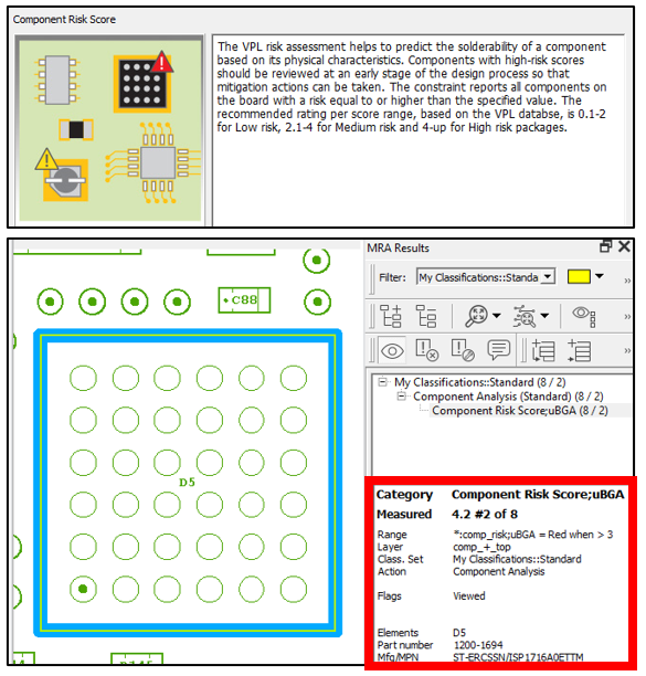
MRA Excel Report Statistics
Validate Optimized Zigzag Array of XD-Discrete Components.
Incorporating a zigzag array arrangement of discrete components on a Printed Circuit Board (PCB) offers a range of advantages that extend beyond mere aesthetics. This strategic layout not only optimizes space utilization but also enhances routing efficiency, promotes effective thermal management, and mitigates issues such as crosstalk. By leveraging the benefits of a zigzag configuration, designers can achieve a more compact, visually appealing, and functionally optimized PCB, ultimately contributing to improved performance and reliability in electronic circuits.
Valor NPI ensures that the zigzag placement array of the XD-Discrete components meets the required restrictions of both component clearance and overlap.
XD Component Clearance
XD Component Clearance
Summary:
The above topics provides only a peek of what you can find in version 2311.
Don’t forget to visit our Valor NPI 2311 page in Support Center and catch up on everything that is new and exciting with the release What’s new and the release highlights documents.