RobotExpert 15 – What’s New?
RobotExpert software is designed to help you perform complete 3D modeling, visualization and simulation of your automation systems including robots, tooling and peripheral equipment. With RobotExpert you can easily analyze cycle time, detect collision and verify safety conditions before the start of production. The latest RobotExpert release continues to deliver advanced technology for robotic process design, validation and offline programming.
In this version 15 release of RobotExpert, new capabilities deliver enhanced solutions for robotic path planning and offline programming, while helping to improve the overall user experience and performance of the software.
Of course, with any new software version there are many exciting new features to talk about and RobotExpert 15 is no exception. We have already been working hard on the follow-on releases to RobotExpert 15 and have included the version 15.0.1 updates for you here.
We know you will be impressed by what RobotExpert 15 delivers! Please let us know what you think in the comments section below.
RobotExpert benefits and features at a glance
-
-
- New capabilities for robotic path planning and offline programming.
-
-
-
- General enhancements, usability improvements and IT updates.
-
Here are many of the highlights from the release.
Robotics path planning and offline programming
Debugging tools
Robot program viewer
The Robot Program Viewer is a new viewer in RobotExpert that enables the debugging of robot programs in their native syntax both before and during simulation. The viewer indicates the execution of the program by displaying an arrow to indicate the current lines of code being processed by the robot during simulation. The viewer can be opened several times for the debug of several programs in parallel. You can debug your programs by inserting breakpoints into the code to pause the simulation for analysis of the current condition. The Robot Program Viewer includes a customizable language for highlighting of text regions or keywords and to expand and collapse entire text blocks. The viewer also shows a complete log of any notes, warnings or errors encountered during the download of paths or programs.

Simulation monitor
In the Simulation Monitor, the existing Trace toggle tile was split into 3: Program (blue icon), Simulation (orange icon) and Trace (green icon), which enable simpler views of robot execution. The Program toggle shows messages related to motion, user interface (UI) layer of offline programming (OLP) commands and customized OLP or motion commands. The Program view shows a program-like view of the path, making it easy to understand which instructions were executed already and what the robot is currently processing. Toggling the Simulation button ON causes the Program toggle to go ON as well (if not already ON) so that you will see both Program and Simulation messages. The Simulation toggle shows messages related to signal values, the simulation layer of OLP commands and customized OLP or motion commands, and realistic robot simulation (RRS) related messages. The Simulation view can show a deeper level of information pertaining to the Program view (simulation interpretation of the program). The Trace view provides complete information for cases requiring deeper debugging of issues found during simulation.
Return to top. ^
Simulation and path authoring
Offline programming and path analysis
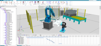
The TCP Tracker can now track a moving part whether it is held by the robot (external TCP), or whether the part is held by the external device (mounted TCP). For example, a robot grips a part and applies glue to it using an external, floor-mounted glue dispenser (external TCP). In another example, a part is held by an external device (part positioner) that rotates the part while the robot polishes it using a polishing tool (mounted TCP). In both examples, the created TCP track is attached to the part. The application now generates curve objects instead of resource objects. Curve objects are stored as engineering data and thus are not reflected in the bill of equipment (BOE) as before. RobotExpert displays curve objects under a new, Curve category in the object tree under a clear folder structure providing easier access and readability of TCP Tracks generated both statically and during simulation.
![]()
Robot jog
In this version, the frame of reference dropdown list in the Robot Jog dialog contains the new tool center-point frame (TCPF) with BASE orientation option. The new frame of reference behaves like a combination of the BASEFRAME and the TCPF, being parallel to the robot BASEFRAME, but positioned at its TCP frame. The result is that when you jog the robot, it is translated with its TCP, but not rotated with it, while remaining parallel to the BASEFRAME.
The new Move Location to TCPF option updates the selected location with the current robot position if Follow Mode is off. In the robot jog settings dialog there are now two separate options for 1) manipulate continuous locations and 2) manipulate weld (discrete) locations.
It is now possible to hold down the Move/Rotate One Step button to continuously move the object according to the defined step size. This removes the need to click the button repeatedly until it reaches the required distance or angle. Now, the status of expanders in the Robot Jog dialog is persisted between closing and re-opening the dialog. For example, if the All Joints expander was open the last time the Robot Jog dialog was used, it will be open when the dialog is displayed again.
Path editing
You can now open as many as 15 instances of the Path Editor. With several Path Editors open in parallel, you can easily edit multiple robot paths simultaneously and view and navigate within several paths at the same time. Opening multiple path editors is also useful to examine different operations associated with different robots (eliminating the need to reload the Path Editor repeatedly). This also increases efficiency when checking different operations on a single robot. You can distinguish between the different Path Editors by having the name of the robot assigned to the displayed operation appear in the Path Editor title.

Direct robot connection
The new Connect to robot command in RobotExpert 15.0.1 enables you to quickly and accurately program Universal Robots (UR) by linking the activity of the physical robot with its digital twin in RobotExpert. With a virtual environment for the UR’s twin, the digital robot mirrors the physical one, helping you to rapidly program the robot by moving its joints and tools to its targets, while checking for collisions and performing reach tests. The command also provides an easy way to program UR robots for several assembly cells when robots of the same model will be used differently in their cells, by setting up virtual environments and digital twins for each one.

Return to top. ^
Additional topics
Robotics usability
Robot System Frames account for large numbers of global frames in any robotics study and are hard to manage and use. Now, when system frames are created or updated they are created or moved under a folder structure titled according to the robot instance name. The World frame is placed in this folder while Tool and Base frames are separated into different folders titled according to the robot controller software (RCS) standard naming.
RCS connection
It is now possible to terminate all RCS connections with a single click using the new Terminate all command in the Controller Settings dialog (mirror image of the existing Initialize all command).You can see an Invalid indication prefix in the RCS version field of Controller Settings or the Robot Properties Controller tab when the defined RCS Version does not exist in the loaded rrs.xml file. Both features help you to handle the RCS setup and state more easily.
Dynamic joint range display
You can now view minimum/maximum joint ranges in the Robot Viewer during simulations. Selecting the Show motion range option overlays a shaded area on the joint sliders representing their range of movements, including further graphic indication of joint range using black triangular markers at the extremities of the range. The Min and Max columns to the sides of the joint slider area note these values as well.

Return to top. ^
General enhancements, usability improvements and IT updates
Paint and coating
Coverage pattern
In the Continuous Process Generator, you can now set the value for automatic tangential face selection for coverage patterns using the new maximum deviation angle from selected face setting in the Continuous tab of the Options dialog. This setting causes termination of automatic face selection when the angle of the candidate face with respect to the last selected face exceeds this value, reducing coverage surface selection to one click in many cases.
RobotExpert 15 provides enhanced path creation capabilities with better coverage of the entire surface. The new extend line to boundaries option enables you to extend the pattern to the edges of a part. The project continuous mfg (manufacturing feature) option enables automatic creation of projected locations. The parameters defining how the locations will be created are set in the Projection Parameters section of the dialog: By distance – creates equally spaced locations; By tolerance – creates locations at significant points; By quantity – creates a specified number of locations.

Return to top. ^
User experience
Simulation speed
The new simulation speed slider lets you easily set the simulation speed. You can change the simulation speed dynamically during simulation without having to pause, allowing you to speed up the simulation (by shifting the slider right) or to slow it down (by shifting the slider left). You can change speed by picking on the slider, incrementing it using the + and – buttons or by dragging the slider. The simulation speed can be set to real time by placing the slider in the center.

Graphic simulation slider
In version 15.0.1, both the Sequence Editor and Path Editor display a light blue slider during simulation to track its progress. By default, the simulation slider is hidden. The option to display it is in the Navigation settings dialog box. You can pick the slider bar to move the simulation to a specific point, and then can drag the button forward and backward to advance or rewind the simulation. Hovering over the slider button pauses the simulation, changing the button’s shape to a ball. The slider has a tab that shows elapsed time of the operation and, in the Path Editor, shows the name of the operation. The Sequence Editor also displays a red bar in the simulation panel, to drag in either direction, as another means to easily move the simulation back and forth. These new visual simulation controls offer smooth sliding behavior and performance and help save significant time, especially when repeatedly playing a simulation.

Placement manipulator
In the latest release, the Placement Manipulator has a new look and feel and offers several enhancements. Bringing the mouse cursor close to one of the axes causes it to lengthen and display in yellow. Clicking and dragging it hides all other components of the Placement Manipulator and only the active axis is displayed until releasing the mouse button. Bringing the cursor close to an axis arc highlights it in yellow and clicking and dragging it hides the other Placement Manipulator components until releasing the mouse button. Selecting a triangular plane handle of the Placement Manipulator and keeping the mouse button pressed lets you drag the object along the selected plane. While the mouse button is still pressed, the shape of the plane symbol turns to a square and all other components of the Placement Manipulator are hidden. A dotted (endless) line displays along the active axis of the Placement Manipulator to serve as a visual indication of the current manipulation direction. Similarly, a circle displays for a rotational axis. This indication changes as you select a different manipulation axis or pick a different object to manipulate. When clicking a Placement Manipulator axis or rotation arc, a numeric box is displayed close to the object for convenient and accurate adjustment of the value along that axis or arc without using the main dialog.

Placement manipulator object emphasis
This version provides options to emphasize the manipulated objects by dimming or graying the rest of the scene in the graphic viewer, making the manipulated objects easier to distinguish.

Placement manipulator location
You now have several options for where to locate the Placement Manipulator in the Graphic Viewer, in addition to the default reference frame. This provides even better control over manipulation of objects.
User layout management
With 15.0.1, you can save your layouts and use them in newer RobotExpert versions, and share them with other users, using the new Export Layout and Import Layout commands. All the user layout information, including viewers state and context menus, together with Hot-Keys configuration, is stored in text-based files for easy capture, sharing, and migration.
Return to top. ^
Performance
Fast collision detection
The advanced Collision Detector is now used as the default collision detection tool, providing significant improvements in precision, memory consumption and performance for all collisions. The Collision Detector now supports collision detection with Point Cloud objects and with/between Logical Groups and supports the generation of interference volumes (automatic interference and interference zone commands).
Simulation
General simulation performance is improved in version 15 through various enhancements made in RobotExpert. In addition, the RCS GET_NEXT_STEP call was moved into a separate thread to minimize the wait time for reaction from the RCS service. This improves performance of RRS simulation greatly (by as much as 50% in most cases).
Return to top. ^
Additional topics
Movie recorder and manager
The Movie Recorder can add a graphic image as an overlay to a movie. There are options to control the size of the overlay image, its level of transparency, its position within the movie frame and to add text and a date stamp. The Movie Recorder Settings dialog contains conveniently placed options to display or hide various elements in the recorded movie without the need to open the Options dialog to access these items: Navigation cube, Working frame, Path/locations, 2D objects (line, curves, frames).
The Settings dialog contains the Cull parts option to improve system performance during movie recording. The previous setting is retained once the movie recording ends.
The Movie Manager uses Movie Recorder functionally to create high quality movies and associate them with their operation. The setting can be opened directly from the Movie Manager dialog.

True shading
RobotExpert 15 offers the same True Shading functionality as other Siemens applications to enable you to enhance the visual quality of scenes in the Graphic Viewer. This is especially useful for presentation needs, like creating simulation videos and documentation with high quality screen shots of scenes. It is necessary to first press the True Shading button, which displays the floor grid, before activating any of the three associated options: floor reflections, floor shadows, and global texture.

Local HTML help
Siemens now provides a way for organizations to install RobotExpert HTML help on their local network. When a documentation server is installed, it can host HTML help for multiple languages. It also provides a fast and powerful, server-based search engine for greater performance in finding and viewing documentation.
Slot joints
In this version, a new type of joint was added to the Kinematics Editor – the Slot joint. It is represented by two pins that are guided to move along one or two slots, forcing the link to slide along the slot geometry. For a single slot, the two pins are constrained within the one slot. For two slots, each pin moves along its own slot. These joints can be used for clamp or weld gun modeling.
The Offset point is an optional parameter that is used for calculating the value for the newly created joint, seen in the Joint Jog and Robot Jog dialogs.

Point creation and organizational blocks
The new Create point command in 15.0.1 enables you to create points in the study using any of three options. These points are convenient for constructing kinematic entities and other geometries. After setting the position of the point by picking in the Graphic Viewer or setting its coordinates, the point appears as a white square allowing you to evaluate the position, turning black when confirmed.
You can now activate the Create block command to create a logical block, which can be used to collect entities, such as points, into logical groups within the navigation tree.
Return to top. ^
Certifications and IT updates
RobotExpert 15 delivers the following certifications and IT updates:
-
- CAD certification for NX 11.
-
- CAD certification for JT up to version 10.2.
-
- CAD certification for Catia V5-6R20178.
-
- CAD certification for SolidWorks up to version 2018.
Return to top. ^
For complete details on the new features of RobotExpert 15 and 15.0.1, please refer to the release notes and new features presentations offered for both.
Yours in robotic simulation and offline programming,
![]()
(on behalf of the entire RobotExpert product team)