On-Demand Webinar: Solid Edge P&ID Modular Plant Design
In this ever-changing environment, the ability to accurately and rapidly create piping and instrumentation diagrams (P&ID) is crucial for meeting company and international quality standards. Companies need complete traceability when moving a 2D P&ID design into a comprehensive 3D model of a process plant. Modular Plant Design capabilities in Solid Edge streamline these workflow processes to allow users to link their 2D P&ID and 3D models.
With the increased complexity and challenges faced in today’s environment, companies use modular plant design to help solve these problems. By subdividing a system into smaller modules, a company can deliver customized functions and capabilities. These highly customizable systems can then be utilized to save on engineering resources, control costs and errors, shorten cycle times, and increase variability and reuse.
In the most recent on-demand webinar, Intelligent Schematics for Piping and Instrumentation Diagram Design, learn from Mike Ashbaugh (Siemens Business Development) and Sangamesh Andoor (Siemens Global Technical Enablement) on the benefits of modular plant design, how to create and navigate intelligent P&ID, add common standard components from a built-in database, and generate lists, reports, BOMs and intelligent PDFs for required documentation. Register to watch this free on-demand webinar!
Modular Plant Design in Solid Edge
There are two main modular plant design capabilities integrated within Solid Edge to support users in fast, easy planning of complex piping systems and plant designs:
- Solid Edge P&ID Design
- Solid Edge Piping Design
For a limited time only, get 50% off all purchases of Solid Edge P&ID Design and Piping Design products. Request a quote to find out how much you could save today!
Solid Edge P&ID Design
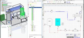
Solid Edge P&ID Design provides 2D flow diagram and symbol support to create P&IDs.
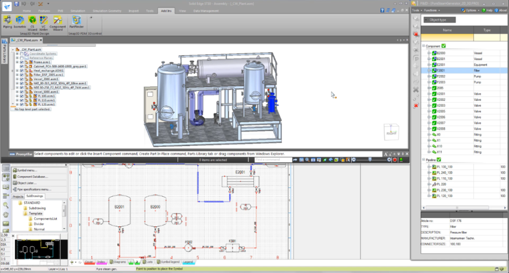
Solid Edge P&ID Design supports ANSI/ISA, DIN, and EN ISO standards, and it connects seamlessly to Solid Edge Piping Design capabilities, in which its definitions control automated 3D pipeline creation. All features that are defined in P&ID can be easily placed into a 3D model, making Solid Edge a truly completemodular plant design solution. Register for the on-demand webinar to learn more.
Solid Edge Piping Design
Solid Edge Piping Design provides you with automated 3D piping design with comprehensive 3D part libraries and fully automated ISOGEN® output, via PDF format, for plant design.
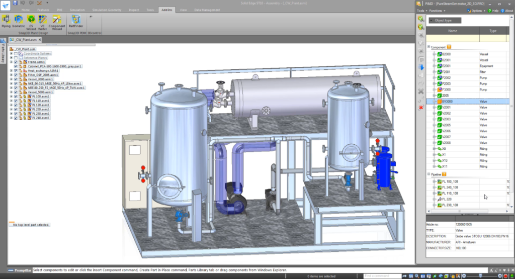
Tubes and hoses of the same length in different assemblies—even if they are flexed differently—maintain the same BOM number, reducing erroneous manufacturing and ordering downstream. Solid Edge Piping Design software includes functionality that allows you to speed up packaging design. In addition, it also includes enhanced 3D piping sketch functionality that allows even the most inexperienced user to easily create 3D sketches.
For additional information about Solid Edge solutions for modular plant design, you can visit our website or simply download a free trial of Solid Edge to give our solutions a try for yourself.
For a limited time, get 50% off all purchases of Solid Edge P&ID Design and Piping Design products. Request a quote to find out how much you could save today!
Some of this information can also be found in a previous blog post covering modular plant design. Check it out here.


