Streamlining your P&ID workflow process with Modular Plant Design
The ability to create P&ID diagrams (piping and instrumentation diagrams) accurately and rapidly is crucial for meeting company and international quality standards. In this ever-changing environment, companies need complete traceability when moving 2D P&ID design into a comprehensive 3D model of a process plant.
In our latest webinar, we’ll show you how to correctly streamline your piping and instrumentation diagrams (P&ID) workflow process using the latest software for modular plant design.
Modular Plant Design and Equipment Layout
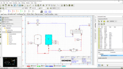
As the first link in the process chain, these 2D flow diagrams are among the most important documents in plant planning. P&ID diagrams are also used to communicate potential projects to prospects as part of a plant design proposal and represent a contract of what will be delivered if the proposal is accepted.
In this webinar you will learn how, when done right, Modular Plant Design and equipment layout solutions can enable your company to create and navigate intelligent piping and instrumentation diagrams, add common standard components from a built-in database, and generate lists, reports, BOMs and intelligent PDFs for important technical documentation.
Modular plant design: More variation, lower complexity
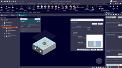
From rudimentary 2D pipe planning to full-scale 3D piping systems, Solid Edge modular plant design solutions streamline workflow processes. Linked 3D piping, support for piping and instrumentation diagrams (P&ID) and Isogen® output ensure that your products are designed right—the first time, and every time. These software modules allow users to easily capture design intent/logic in a 2D schematic, then develop 2D P&IDs into a comprehensive 3D model of a process plant.
Solid Edge P&ID Design provides 2D flow diagram and symbol support to create P&IDs, which are crucial for meeting company and international quality standards. It supports ANSI/ISA, DIN, and EN ISO standards and connects seamlessly to Solid Edge Piping Design where its definitions control automated 3D pipeline creation. Features that are defined in P&ID can be easily placed into a 3D model to provide a complete modular plant design solution.