I am a Sheetmetal Part and I Love Synchronous

Hello Edgers! my name is Cover.psm and I am a sheetmetal part. This is my story. My full name could be misleading for I am not native to Solid Edge. Born in a CAD program that pioneered parametric modeling, I was built one flange at a time and could exhibit basic behavior like bending-unbending all the way up to flattening out. I could be saved out as a DXF or PDF and also lend myself to be parametrically controlled. Moreover, I was living happily in a fully constrained assembly with my fellow components and all was well with the world.
Over the course of time my parent CAD was engulfed in a wildfire and eventually died out, but I was spitted out in time via a neutral format. Soon after, I went knocking on the door of every CAD program worthy of its name but all of them disowned me. While some refused to Work with me, another one was too busy reinventing itself having no capability to even figure out what I was even if it would let me in. I was meted out a STEP-brotherly treatment after being given a punch in the face, no pun intended.
I was outcast by my parent CAD program but Solid Edge with Synchronous Technology embraced me. I was brought in using a Sheetmetal template in the synchronous mode.
The designer who imported me into Solid Edge was smart enough to notice the  symbol on the Part Copy node in the Pathfinder and pondered “Is this really an error per se ? or is it just some condition in which an imported solid has not been checked for simplicity” and those thoughts were not misplaced as it turned out. Many times when a solid model like me is imported from another format, I am just composed of multiple surfaces where there should be one, or multiple edges that can be combined into one. A good example is a hole where the cylindrical surface could be found split into two surfaces sometimes.
I definitely needed some repairs. Hovering the mouse cursor over the Part Copy node revealed this helpful tip.

Without further ado my designer summoned the Command Finder which is normally stationed at the bottom of the Solid Edge application window and the Optimize command was invoked directly by clicking it in the search results window.

This tool performed a simplification to improve my performance. It felt like getting a free pedicure but I knew it wasn’t a cosmetic treatment. The results were very promising. It increased my precision and quality by simplifying my B-Surface definitions and healing my edges. This assured the designer of improved display performance, prevented slow window updates such as those during zoom fit apart from experiencing faster view rotations.
Optimizing me guaranteed zero direct modeling failures, absolutely no problems when adding or removing material during cuts or protrusions, no crashes or abnormal termination of commands especially during drawing view creation or subsequent updates.
Also, problems with creation of section views or long waiting times for detail view creation would be non-existent after such optimizations.
Edgers, remember: Even if I don’t appear to be containing faults, it is always a good practice to run the Optimize command since it improves my precision and reduces complexity as an imported model.
This was followed by passing me through an amazing conversion called ‘Thin Part to Sheet Metal’ found in the Transform group of the Tools tab on the ribbon bar. This was a lifetime event for me so I’d rather call it a ‘DUMB Part to Sheet Metal’ command. All it asked was to select a base face for conversion.

The process finished in a jiffy and I was reborn a bona fide sheetmetal part. I was instilled with a strong sense of pride for what I could now do for a designer who just saved precious time recreating my lookalike from scratch.
The Pathfinder by then had reflected to show my recognized features, a base Tab and a few flanges. It felt like emerging out of deep slumber and I could once again flap my flanges. So not only I looked smart, my designer too was delighted, an epitome of a win-win situation.

Adding a new flange in the synchronous mode was easy as one-two-three. An edge on one of my flanges was clicked, then gently tugged in the required direct and voila! a new flange was created. Ticking an option on the Command Bar turned it into a partial flange. Edgers, can you believe this ? a nascent sheetmetal part resurrected from the graveyards of backup tapes having goosebumps within minutes of rebirth. I have just experienced it.

3D PMI dimensions could be directly applied between the partial flange and one of my edges and the designer was all set. Changing the dimension values was all it took to update my width and distance from the edge. I was no longer a dumb model but was nevertheless dumbfound to see that unlike in my previous life where hunting down sketches and making them behave to successfully update my flanges would be an ordeal, synchronous technology did that effortlessly. “”Look ma, no sketches!” I exclaimed.

Whereas the Recognize Chamfers command aptly did the job described in its tooltip, simply running the Recognize Holes command recreated all holes and neatly grouped them by size in the PathFinder. Hole patterns could also be recognized effortlessly.
Some cutouts needed to be removed and the selection manager figured it out flawlessly. Again No witch-hunting for underlying sketches. I witnessed some hassle-free direct editing from close quarters and can tell it was a mesmerizing experience.
At first I thought shortening my overall length would be a nightmare but then came along the prodigious steering wheel when my designer simply windowed around a bunch of my features. I had a tickling sensation while the designer dragged the mouse and adjusted the desired length. This functionality was beyond my wildest dreams.

In retrospect, Solid Edge with Synchronous Technology not only recognized me as a sheetmetal part but also allowed modification of existing features while adding new ones seamlessly. As an imported part I simply love the way synchronous technology adopted and subsequently treated me. I feel so elated having started my journey when I was spit out as a dumb model but ultimately rechristened as a Cover.psm in Solid Edge.
You can witness my story so far in this HD video in fullscreen with headphones ON:
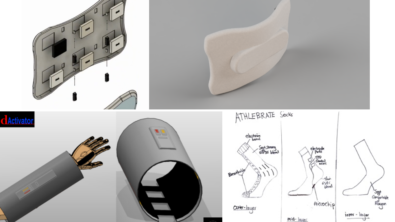
And here’s my buddy Bracket.psm who has a life story not much different than mine. Doesn’t it look like one happy Solid Edge sheetmetal part:

In the next episode I will:
- Narrate how Design Intent in Synchronous Technology allowed making changes to features that would have taken 4x the time in my parent CAD program.
- Also reveal how Bracket.psm pictured above borrowed a few slot faces from me which started behaving like a locally grown feature.
- Thrill you with the experience we had when edited in the context of an assembly and getting tweaked in sync with geometries of neighboring parts.
If you have any suggestions for me and bracket.psm or some exciting new stuff to explore in our new-found life in the synchronous environment, do leave a message for us in the comments section below.
Till then, let’s sync…

Comments