Top 7 FloTHERM V11 Features – #1: Joule Heating
FloTHERM V11 is now released and contains a wealth of interesting and useful features. In this blog series I’ll select my favourite top 7 and explain each one in some detail. To start with, Joule heating, also know as resistive or Ohmic heating. Joule heating is the power lost to heat as electrical current flows down a conductor. I^2R, VI, we were all first introduced to this way back in school. From an electronics thermal simulation perspective it requires a full 3D DC electrical flow simulation and from that the power dissipation distribution that feeds into the thermal simulation in the usual way.
Previous versions of FloTHERM had a rudimentary Joule heating capability where a current was prescribed, together with a block by block current flow direction. From that the power dissipation as determined. In V11 electrical boundary conditions are imposed on the periphery of a 3D solid representation of the conductor, the subsequent 3D electro-thermal simulation process solves for current and voltage potential and uses the Joule heating power as a cell by cell source term in the solution of temperature.
Typical applications will include busbars, PCB/BGA substrate power and ground planes, leadframes, even fuses. Anywhere where the resistive heating may play a dominant role in the total power dissipation in the system (rather the power density).
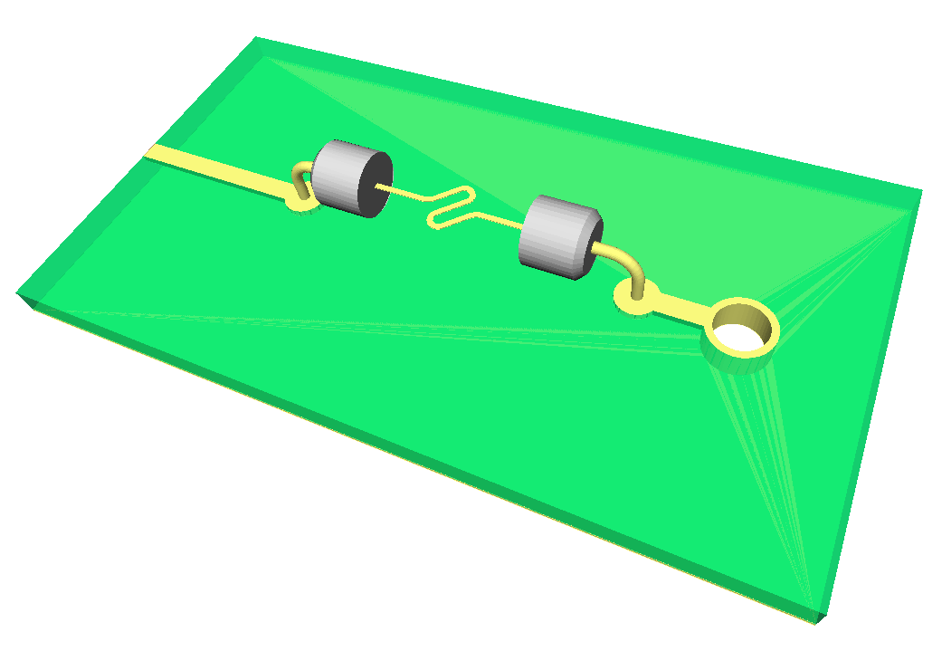 Here’s a simple well recognised example of a fuse, mounted on a simple PCB (fuse housing hidden for clarity). A current value is defined at the trace face leading up to the fuse, a fixed voltage value defined on the edge of the ground plane on the underside of the PCB. A via connects the trace to the ground return.
Heat flow, air flow, current flow, they all are flowing continuums that FloTHERM has the ability to animate. Useful for appreciating the flow direction, flow obstructions etc. The animation shows how the electrical current flows through the circuit.
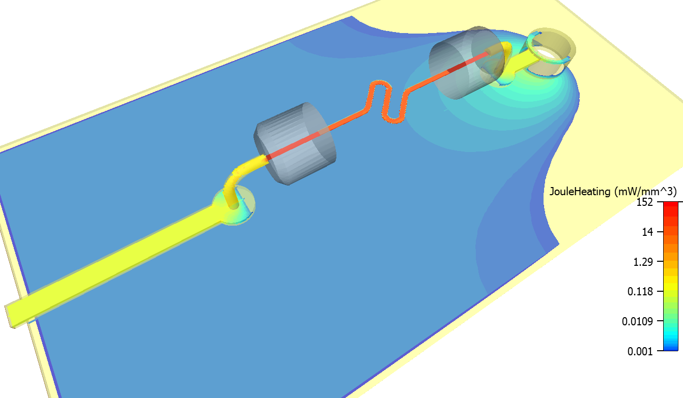 The speed of the arrows (electron-arrows?) is derived from the current density which in turn is closely related to the resulting power dissipation and temperature. Note the high current density in the winding fuse section, achieved by design. FloTHERM can also plot the resulting Joule heating power dissipation. Being a 3D simulation the power density is shown in power per volume, in this case /mm^3.
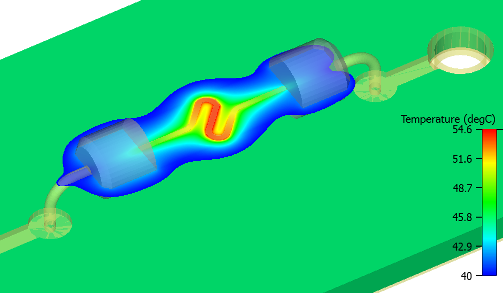 The resulting temperature though is the item of most interest. Here I’ve just plotted the hotter temperatures which exist in the central section of the fuse.
Fusing involves a coupling between the electrical and thermal worlds. An increase in temperature will result in an increase in electrical resistivity which will increase the current density, which will increase the Joule heating power which will increase the temperature and so on. If the heat is removed fast enough a balance is achieved and things settle down to a constant temperature rise. If the coupling is too strong, specifically under high current conditions, temperature will run away until the fuse gets so hot it melts. FloTHERM can handle this coupling through its temperature dependent electrical resistivity material property (Also the temperature dependent thermal conductivity though this is a secondary contributor to the runaway condition).
 Here’s another example showing the effects of Joule heating in a PCB power delivery net, imported from Xpedition xPCB. FloTHERM has a unique technology for the representation of such complex 3D EDA defined geometries, which can be included in a Joule heating simulation as well. Resulting plots of voltage potential (all about the same, the PDN is working as expected, providing that voltage potential all over), magnitude of current density, the resulting Joule heating power dissipation and finally the resulting temperature.
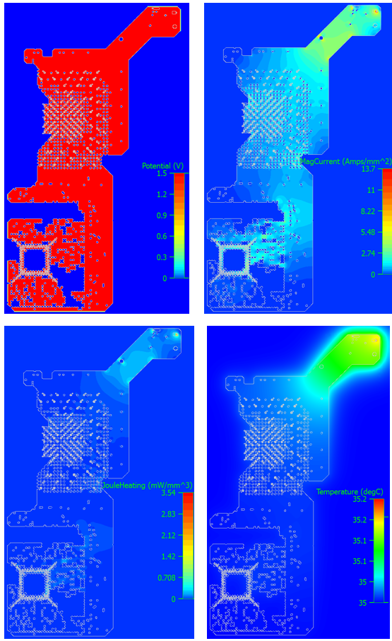
In this case a very small temperature rise above ambient. For ‘typical’ digital electronics it’s the power dissipation in the die of active devices that dominate the thermal behaviour of the system, not the Joule heating in the PDNs.
Eager to find out more about the new FloTHERM V11 features and don’t want to wait for me to finish this bog series? Well, you can check out Byron Blackmore’s FloTHERM V11 webinar right now!
17th September 2015, Ross-on-Wye.


