The art of modelling using CFD. Part II – Grilles
Wiki quote: “A grille is an opening of several slits side by side in a wall or metal sheet or other barrier, usually to let air or water enter and/or leave but keep larger objects including people and animals in or out.” For electronic products that need to be kept cool, getting cool air in through grille work is commonplace, thermal designers love them, EMC/EMI designers don’t. For such products, keeping animals in isn’t as important as keeping fingers out. From a modelling perspective, accurately representing the effects that the grilles have on the air flow is obviously critical. Representing them efficiently can save hours of thermal simulation time…
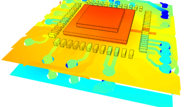
Take a model of a desk top unit comprising of an enclosure with some electronics inside. Grilles on the side and top allow for air flow through the system. No fans, the air moves due to buoyancy alone, so called ‘natural convection’. When modelling the grille slots exactly the excessive computational mesh required to resolve the air flow as it bends around the uprights results in lengthy solution times.
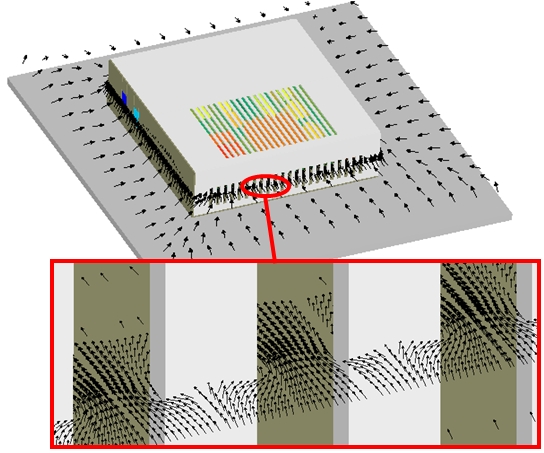
It looks realistic and the simulation accuracy is as best as you could hope for. Unfortunately, in the real world, the project you are working on requires 5 design variants to be simulated in time for the project review meeting right after lunch. As a thermal designer how could I reduce or simplify my model to get results quickly without unduly affecting the simulation accuracy? Well fear not, those clever people at Mentor Graphics have included a neat object in FloTHERMthat can be used to efficiently represent the effects of grille work quite easily. Us FloTHERMians refer to it as a ‘resistance’ object. It doesn’t require much mesh but will correctly resist the air flow in the same way as the actual grille work does. It does however require a parameter to be defined that captures the flow resistive effects; a pressure loss coefficient. FloTHERM can derive this from a specified % ‘open area’ of the grille, it can be obtained from the literature (Idelchick seems to have spent his entire life putting things in wind tunnels to note down their loss coefficient and the entire fluid dynamics community is therefore indebted to him for ever) or you could actually use FloTHERM itself to derive it.
Delete the exact geometry of the grilles and replace with the simple 2D resistance object:
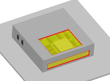
Solution time is slashed, results of interest (e.g. Tj_max of the processor) change little (spot the difference below) and you get kudos for presenting the conclusions of running 12 grille configuration variants at the review meeting.
Modelling is the art of representation, the reward is a pay rise and a promotion (we wish).
13th May, Hampton Court