HiL and realistic environment simulations for your UAV

To ensure the safe operation of autonomous unmanned aerial vehicles and advanced air mobility vehicles, the flight control systems with their autonomous flight functions such as detect-and-avoid and localization functions need to be extensively validated for diverse flight scenarios and operational conditions. Therefore, a digital twin is highly valuable as part of an efficient development process that ensures a safe product.
Within the MARLOC project, we have investigated a simulation framework based on Simcenter Amesim and Simcenter Prescan software for the development and validation of flight controllers with localization capabilities for autonomous air systems. To evaluate the localization capabilities accurately, a realistic flight trajectory needs to be simulated. To accomplish this, we have created a hardware-in-the-loop (HiL) simulation framework where a physical Pixhawk flight controller was integrated with the digital twin.
Simulation framework
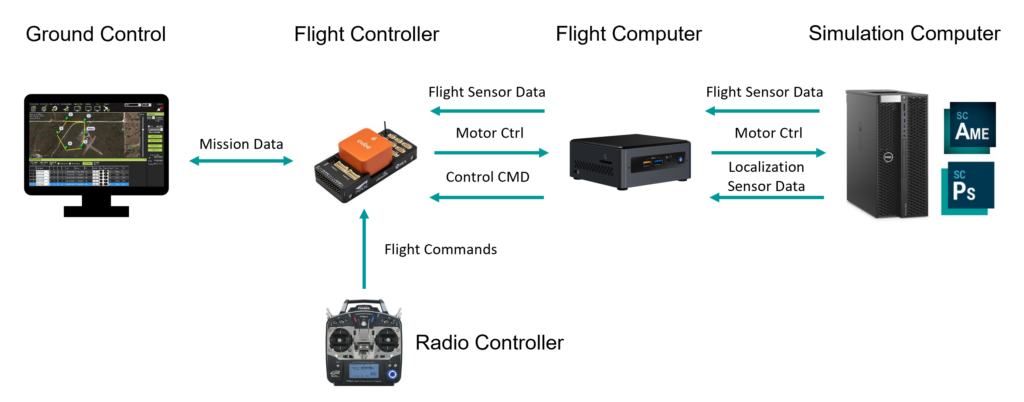
The overall architecture of the HiL simulation developed is shown in Figure 1. Simcenter Amesim was used to model flight dynamics together with propulsion systems. While Simcenter Prescan was used to create the virtual environment and model the camera sensors attached to the vehicle. A ROS network was used to establish communication between the simulation software and the flight controller hardware. In order to start the simulation, a set of waypoints are specified and sent to the Pixhawk via the QGroundControlStation software which is running on a separate laptop. The flight controller will then try to steer the vehicle following a trajectory connecting these waypoints. The aircraft dynamics will be simulated in Simcenter Amesim based on the input given to the motors of the UAV model by the Pixhawk. The new position will be computed and sent to Simcenter Prescan to update the location of the aircraft in the environment. While the aircraft flies, the camera sensor simulated in Simcenter Prescan will produce the camera feed that will be later forwarded to a pose estimation algorithm running on the flight computer.
Use case
The digital twin model of the drone developed in Simcenter Amesim is shown in Figure 2. This model was created based on an existing drone from FlandersMake research institute, partner in the MARLOC project. Considering the size, mass and inertia properties, propeller and motor parameters obtained from experimental testing, the physical dynamics of the unmanned vehicle are rigorously modeled.
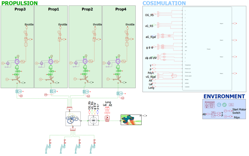
The cosimulation block will specify the data exchange with the other components in the framework. In this manner, on the right side of the block, Simcenter Amesim receives from the Pixhawk flight controller the four throttle inputs to the motor models. On its left side are determined the states computed in Simcenter Amesim, based on the commanded throttle, to be sent through the framework.
Another aspect of the framework is the environment model. In order to create realistic camera images and fly in the same environment specified by the trajectory in QGroundControl, a model of the London Bridge area, shown in Figure 3, was created. This environment was developed using satellite data available from OpenStreetMaps to create the buildings and to apply the texture over the 3D model.
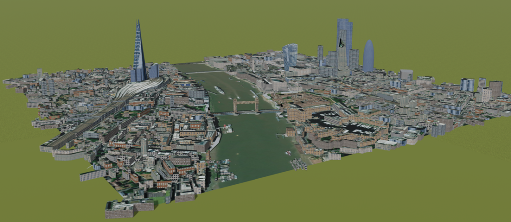
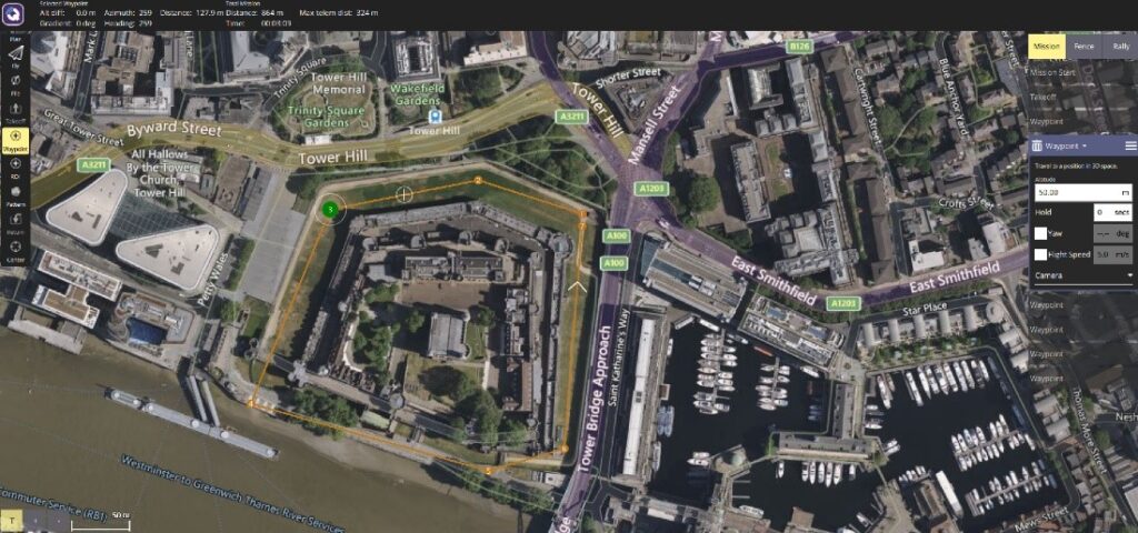
Figure 4 shows the waypoints that were specified, creating a trajectory for the Pixhawk to fly around the London Bridge area using QGroundControl software which runs on the Ground Control laptop. Matching with the 3D model created in Simcenter Prescan, the trajectory that the vehicle will follow and the images generated by the camera will be consistent with the real environment.
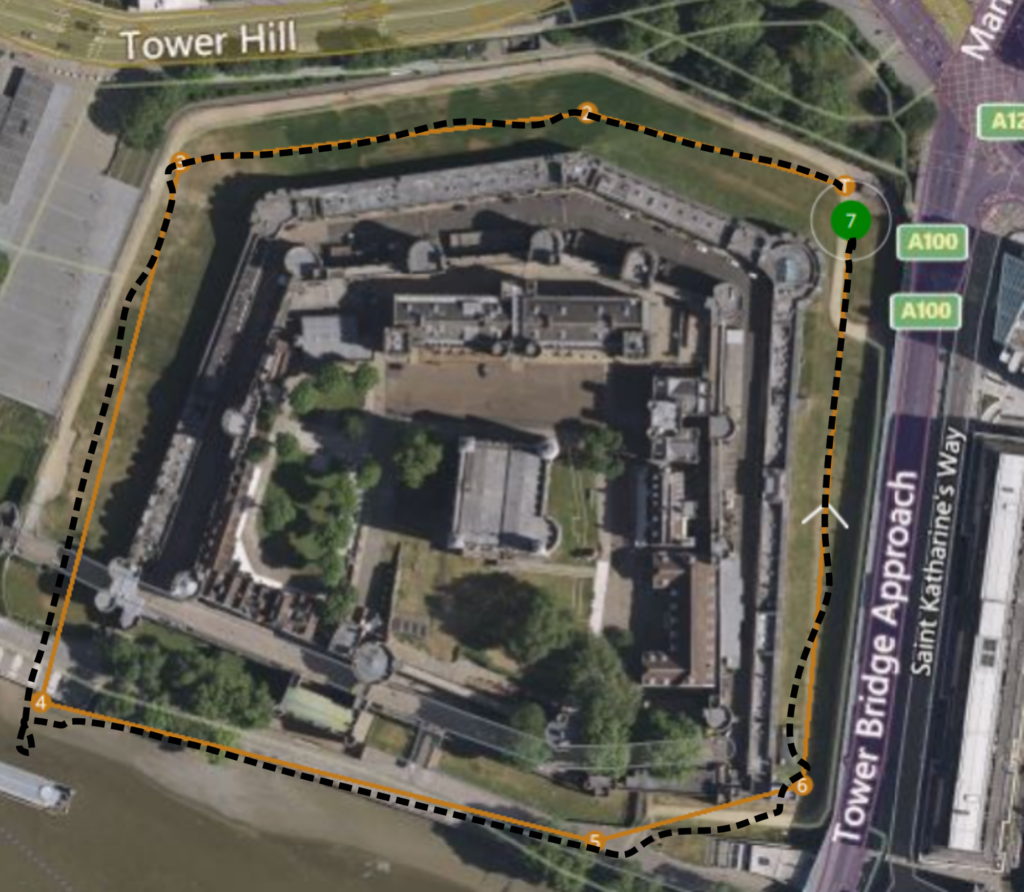
In the simulation, the drone model was able to follow the trajectory by receiving the steering commands from the flight controller. The results obtained are shown in Figure 5, where the resulting trajectory followed by the UAV is marked as a dashed black line on top of the trajectory specified by the waypoints in QGroundControl.
In conclusion…
It has been demonstrated that the simulation framework can be used to integrate real hardware such as a flight controller to test its functionality. The main challenge, which was for the UAV model in Simcenter Amesim to compute flight data that was compliant with the operation of the flight controller at the required rates, was successfully achieved. Additionally, diverse sensors can be simulated in Simcenter Prescan in order to validate autonomous functions such as detecting and avoiding or simultaneous localization and mapping algorithms.
In future work, the trajectories obtained from the HiL simulation will be used to evaluate a visual simultaneous localization and mapping (SLAM) algorithm under different weather conditions.
You might be interested in…
Urban air mobility
Fly it before you build it: design aircraft while targeting certification

eVTOL design and engineering; It’s time to talk!
Accelerate VTOL aircraft verification and certification