Electric machine modeling and system integration

How a truly multi-disciplinary system simulation platform supports the early sizing, vehicle integration and control validation to balance performance, energy efficiency and drivability
Drive cycle based design and optimization of electric machines
The efficiency, power output, transient response, reliability, and other aspects of the machine contribute significantly to the vehicle’s performance. That’s why actual and next generation of traction motors are facing highly significant design challenges:
- Very high-efficiency levels (~95%)
- Wide speed range (up to ~14,000 rpm for Class II vehicles)
- High power density compared to current options
- Reduced or no rare earth permanent magnet materials
- Robust, with respect to manufacturing processes
- Low NVH characteristics, among many others…
At the same time, in function of the targeted usage of the car, the motor will be used on a range of operating points. These operating points are function of both the vehicle characteristics and the typical driving cycle. Hence, there is an emerging trend to incorporate the effects of drive cycles into the design process of traction motors.
The design flow presented hereunder is ideal for meeting these challenges:
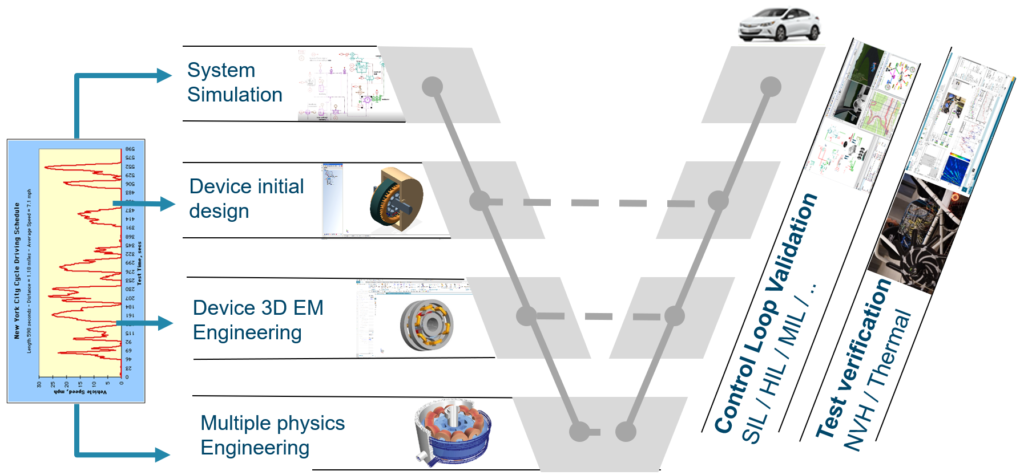
- In the first step, system-level simulations are usually carried out to determine the desired performance requirements of the machine to be designed. The results of these analyses are the inputs for the next step
- Design initiation and iterations are carried out. At this stage, multiple design topologies and options are considered and the choices are narrowed for further analysis. The machine options obtained by the end of this stage would satisfy the performance requirements determined during the previous stage.
- Next, additional 3D analyses are carried out to further validate design performance or carry out device fault analysis.
- Finally, multiphysics and other types of analysis or simulations are carried for drive and cooling system design of the machine.
For each of these steps, the effects of drive cycles can be incorporated using solutions from Siemens’ Simcenter portfolio. In this blog, we will focus on system-level simulation for electric machine modeling and system integration. Watch out for the following on-demand webinar if you are interested in the full 1D to 3D approach.
From vehicle requirements to motor specifications
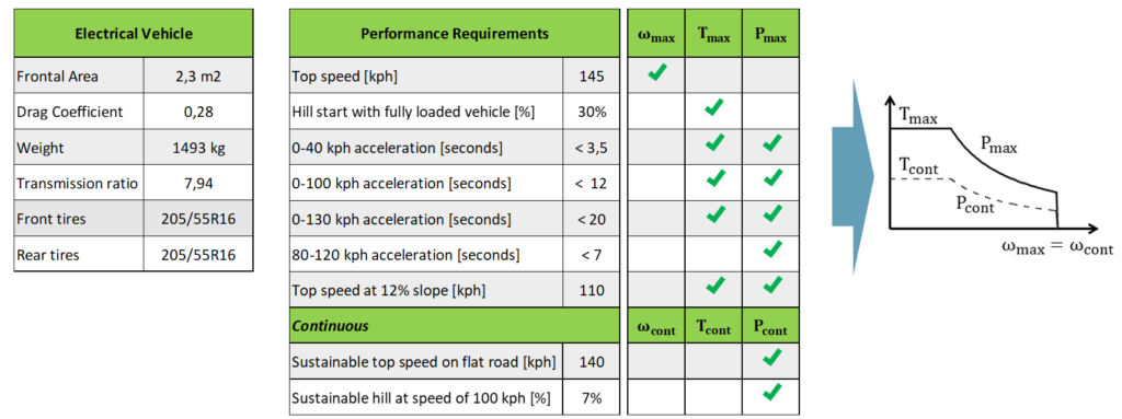
Starting from the main characteristics of the vehicle and from vehicle performance requirements, the objective is to obtain the performance requirements of the electric motor. Vehicle information are for example its mass, aerodynamic parameters, size of the wheels, and reduction ratio.
The performance requirements at the vehicle level are impacting the main motor characteristics. For example, top speed and transmission ratio impose the maximum speed of the motor. The hill start criteria impacts the maximum torque, and sustainable speed on flat slope and hill impact the continuous power.
To define motor torque-speed requirements, a vehicle-level system simulation model was developed in Simcenter Amesim.
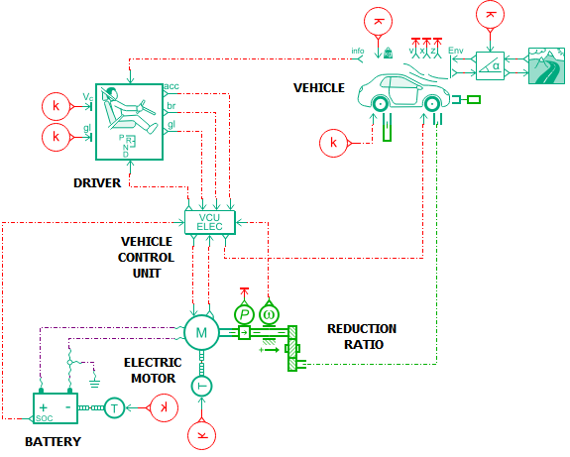
This model includes:
- A driver, which computes accelerator and brake position in order to follow a velocity target. This target speed can be defined as normalized cycles (WLTC, FTP …), or a customized drive cycle with speed target in function of time or distance.
- A longitudinal vehicle, computing vehicle acceleration in function of traction torque, braking torque, and resistances such as rolling resistance or aerodynamic drag
- A battery, in our example, simplified as a constant voltage source
- A motor
- A VCU defining the torque request to the motor and the braking torque in function of the operating conditions
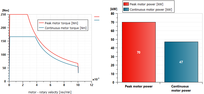
The motor model is at this initial stage simplified and allows to parametrize the maximum torque, speed, and power. The efficiency is fixed, as the power consumption is for the moment not a target of the analysis.
The model is used first on various driving conditions, allowing to simulate peak performance. For example, acceleration from 0 to 100 km/h, sustainable speed with a certain road slope, hill start with vehicle fully loaded… Therefore, simulation allows setting peak and continuous power and torque.
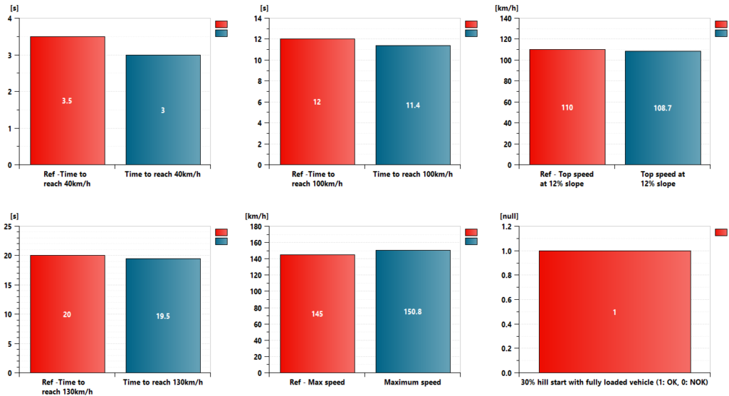
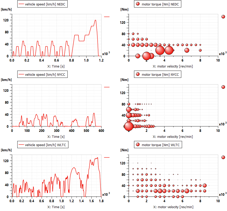
Then, normalized driving cycles such as New European Driving Cycle (NEDC) and Worldwide Harmonized Light Vehicles Test Cycle (WLTC) are simulated. The US EPA NYCC test has been developed specifically for low-speed urban driving with frequent stops. In addition, user can implement any personal driving cycle. When multiple cycles are considered, the e-motor’s performance requirements change as expected. During the NYCC test, the motor is used at low speed and low torque conditions, whereas the WLTC cycle covers higher speed and torque. To extract the final design ranges based on drive cycles, we superpose the results from various cycles to use as inputs into the design process.
Motor assessment: design validation
Once the design of the electric motor is completed, system simulation can be used again to validate the motor from a performance point of view, energy consumption point of view as well as defining the requirements of the cooling systems or looking into other attributes such as drivability.
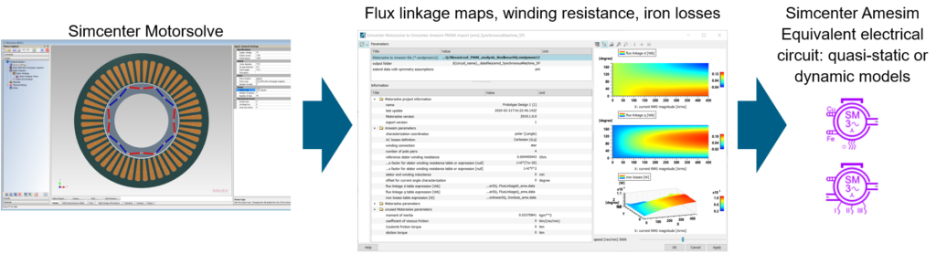
Let’s assume that the electric motor has been designed using Simcenter Motorsolve. Simcenter Amesim can receive flux linkage maps, resistance, and iron losses generated by Simcenter Motorsolve. The four types of exports are explained in the following blog. In our case, we use a quasi-static equivalent electrical circuit model. This model considers the non-linearities of the motor and then is more predictive on the current demand, torque generation, and heat release, which enable a proper estimation of the energy efficiency.
The motor data are importer in an updated electric powertrain model including:
- a non-linear quasi-static motor model
- a DC/AC inverter model, parameterized with a global efficiency or with the characteristics of the power electronic components
- a torque to current control model, providing the optimal currents set-points for a data-set of torque objectives and rotating speed. The current setpoints are automatically generated with an app, starting from the motor and inverter parameters
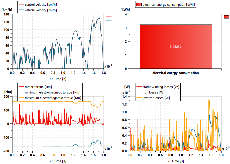
We present hereunder the results of a WLTC driving cycle. The motor is powerful enough to follow the cycle, the torque request being always below the maximum torque the motor could deliver. To perform the cycle, the motor requires total energy of 3.22 kWh. This information could be used to define the sizing of the battery to reach a specific range target. The model estimates the total heat rejected by the motor, which gives boundary conditions to the thermal department.
If you are interested in cooling system design and control to improve motor efficiency and durability, look at this blog presenting a nodal, geometry based electric machine thermal model.
The importance of regenerative braking strategies on range
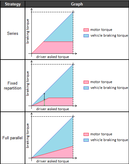
Define an optimal regenerative braking strategy is as important as minimizing the losses in the electric machine. As you can see hereunder, various simple control strategies exist:
- Series: The motor is used to break the vehicle and regenerate the battery. If the motor is not able to provide the requested torque the VCU uses vehicle brakes to complete the braking
- Fixed repartition: the motor and the mechanical brakes are used together with a fixed repartition
- Full parallel: the motor and the vehicle brakes are used together, and the motor provides maximum torque when driver brake torque is maximum.
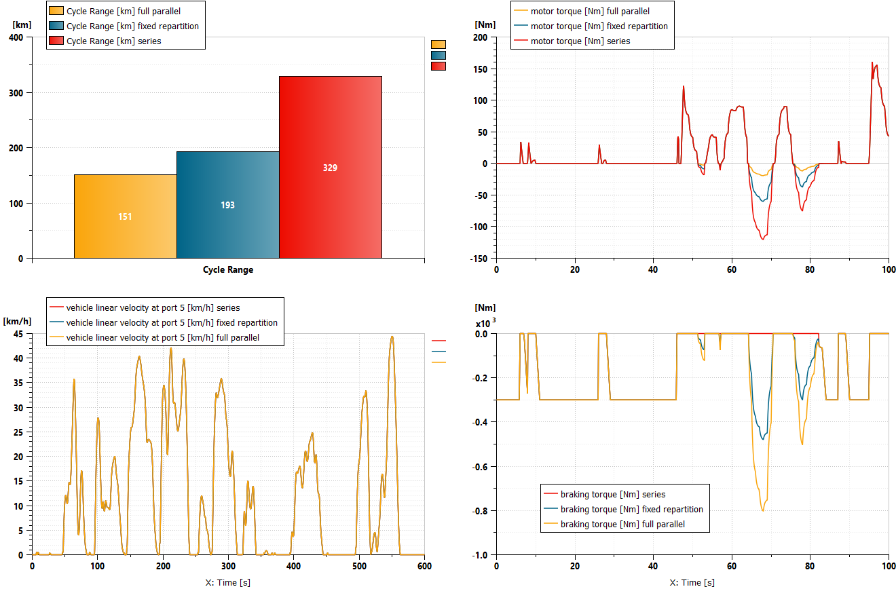
Obviously, the series strategy is the most efficient in terms of energy consumption as you can maximize the regeneration of kinetic energy into electrical energy. Especially on the NYCC test including a lot of acceleration and deceleration at low speed, and where aerodynamic drag is limited due to the low-velocity speed.
But as you can imagine, the electric motor braking power changes drastically, and it will have an impact on the mechanical comfort of the vehicle when the driver releases the acceleration pedal.
If you are interested in innovative regenerative braking strategies, please take a moment to read this paper from Chalmers University of Technology (Sweden). The article focuses on the regenerative brake system of an electric vehicle with a high-speed drive at the front axle. This paper is part of the ModulED project that has received funding from the European Union’s Horizon 2020.
The impact of regenerative braking strategy on drivability
Now the objective is to simulate accurately the mechanical comfort of the vehicle when the driver releases the acceleration pedal. We will observe variables such as the vehicle longitudinal, vertical and pitch acceleration.
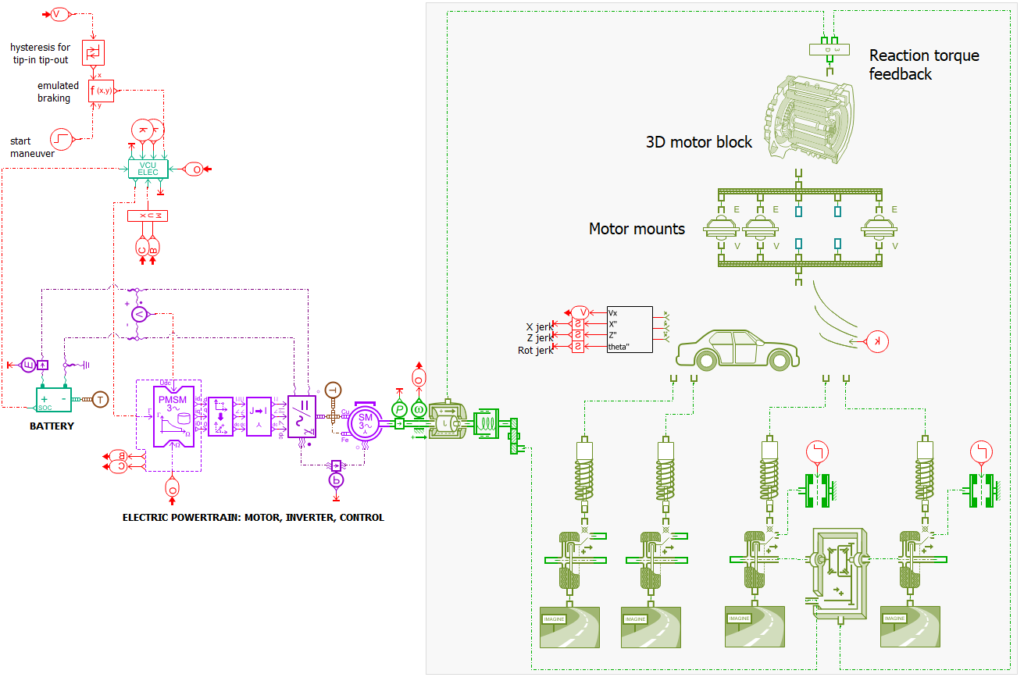
For considering drivability aspects, the 1D vehicle model needs to be changed with a 2D vehicle model connected to a 3D motor block model with mounts. The reaction torque coming from the electric motor and the differential on the motor block needs also to be considered.
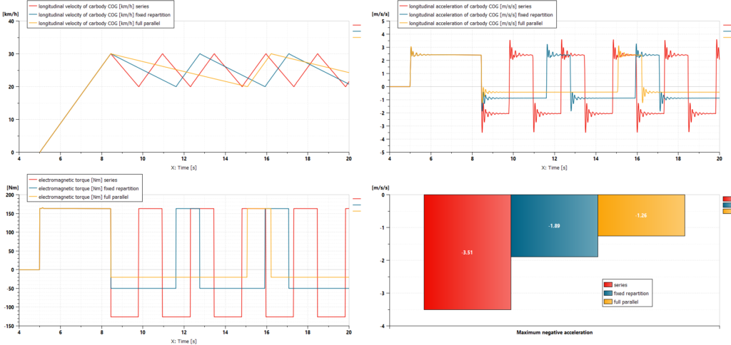
Here we simulate the following maneuver: full acceleration (tip-in) until the vehicle reaches 30 km/h, then the pedal is released until we reach 20 km/h, and then tip in again. The electromagnetic torque is higher in case of series strategies, and it has an impact on the maximum deceleration when the driver releases the pedal.
Capturing fuel economy and drivability simultaneously is then of great importance when defining and calibrating regenerative strategies and parameters, so as to find an optimum between these attributes in function of the vehicle requirements.
What is valid for electric cars is even much more important for hybrid ones, due to the multiple power sources (combustion engine and electric machines). For more details, we have two articles that may interest you:
- How Hyundai Motor Corporation pre-defines major calibration values using HiL simulation for energy efficiency and drivability and reduces vehicle physical testing by 40 percent
- How Honda R&D Co., Ltd uses Simcenter solutions to solve hybrid engine restart vibrations
Summary
We have presented in this blog a workflow for electric machine modeling and system integration using Simcenter tools. This is only a part of the e-machine design disciplines that Simcenter portfolio can address. Indeed we have not talked about NVH and mechanical stress analysis which can be solved within our portfolio. If you want to find out more about these, you can review our webinar series “Develop reliable and energy-efficient electric machines using simulation“.
Learn more
Discover the Simcenter system simulation portfolio and the last features of our products in this video.