Thermal simulation of electric machines
Facilitating innovation in thermal integration of electric machines
Efficiency regulations for electrical machines are placing greater demands on electrical machine designers. Now, alongside an optimized electromagnetic design, the thermal simulation of electric machines has also become increasingly important in the design process. Especially as the different industries are focusing more and more on higher torque, higher power density and increased efficiency demand, along with reduction in size, weight and cost. Finally, more performance and a smaller package is resulting in higher operating temperatures with higher temperature gradients. Therefore, new generation of electric machines requires in general higher performance material, typically higher insulation class material and higher performance magnets. Those technical requirements are calling for alternative methodologies during engineering process to balance all those constraints (innovation, costs and delays). Again, digitalization is key.
Simulation can be a precious ally to help in addressing those complex challenges at various stages of the design process.
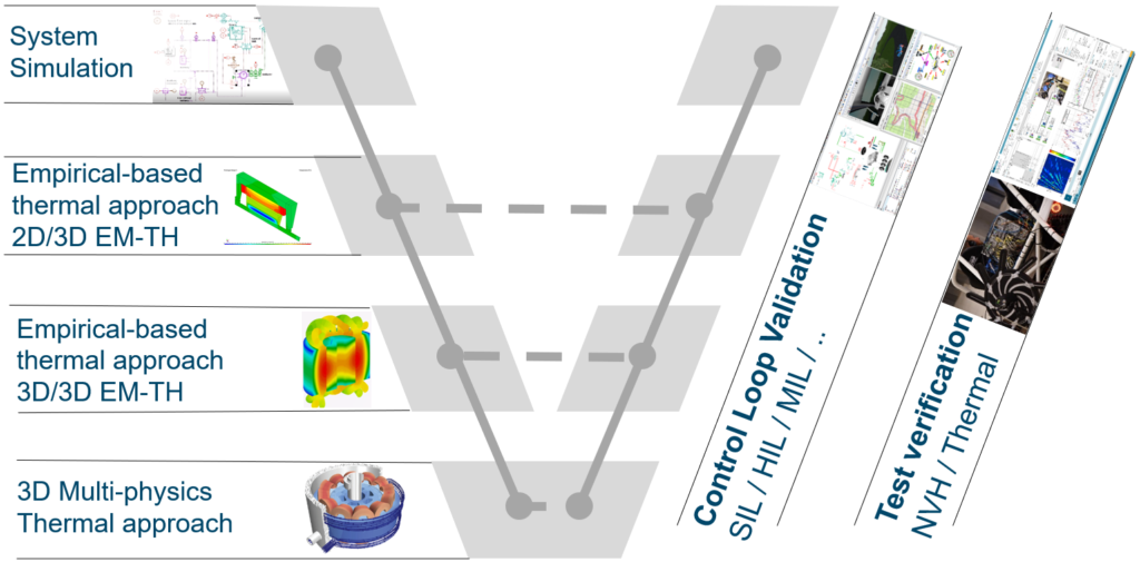
Our complete Simcenter electric machine thermal simulation is presented in the following on-demand webinar. The traction e-machine design V-Cycle is described, including:
- System simulation at the requirements for the cooling strategy
- Empirical-based thermal analysis of the cooling system of the machine for a rapid turnaround of some cooling concepts
- CFD-based multi-physics analysis to study on a 3D detailed geometry the design of the machine cooling system and its optimization for overall machine performance improvement
- Full powertrain system simulation and validation of the design on transient drive cycles
In this blog, we will focus on the validation the cooling requirements of a traction motor in realistic vehicle conditions and transient drive cycles
Model requirement
Once the internal cooling of the machine has been designed, the next challenge is to validate the cooling system design and control, to improve motor performance, efficiency and durability.
To do so, we will use:
- First, a reduced model to simulate the machine electromagnetic performance accounting for the magnetic non-linearities, the permanent magnet temperature, the losses in the rotor, yoke and tooth sectors and the winding temperature. Usually, information of losses comes from a detailed electromagnetic simulation done with Simcenter SPEED, Simcenter Motorsolve or Simcenter MAGNET.
- Second, a lumped thermal model of the permanent magnet synchronous motor (PMSM) with thermal capacitances and resistances calculated from geometry. I will give more details later
Again, the objective is to simulate the e-motor in realistic driving conditions, and check that the temperature of the main parts of the motor such as the windings or the magnet remains under a given limit.
Geometry based electric machine thermal model
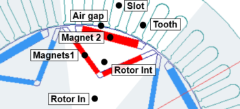
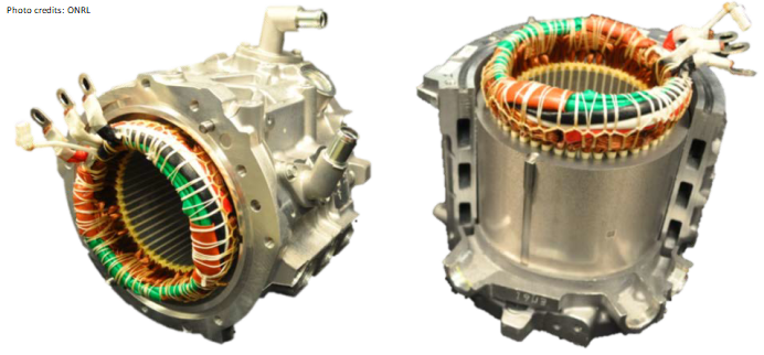
The first step is to obtain a complete model of an electric machine considering thermal and electric phenomena. Let’s take as an example the Nissan Leaf machine, 2012 version. Rotor and stator parts are modeled taking into account radial and circumferential heat transfer between the different elements of the machine. Thermal heat exchanges with the shaft are neglected.
18 thermal nodes are used to model the Nissan Leaf electric motor. The thermal modeling approach is presented in the drawing in the middle. Each thermal node is exchanging heat with others through thermal resistance. Rotor and stator parts are modeled using thermal capacitances, and radial and circumferential heat transfer between the different elements of the machine are represented by thermal resistance. These thermal capacitance and resistance are computed using analytical expressions, starting from the information on the machine geometry and material properties.
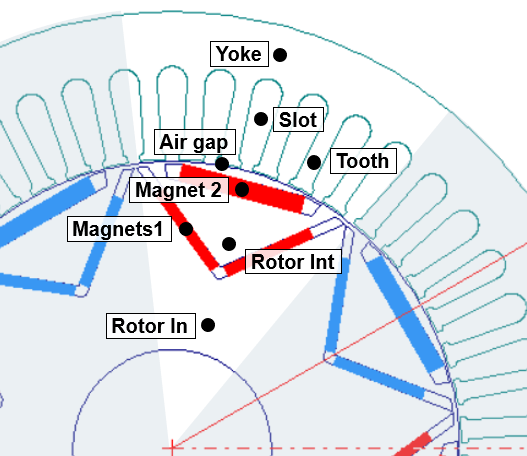
Main thermal nodes of the machine model 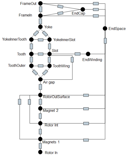
Thermal model approach
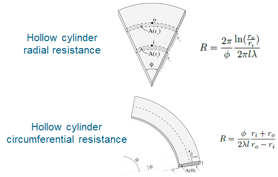
The thermal resistance calculations for conduction are function of the geometry, and are defined in [1]. One can see below some basic examples:
The geometry and performance data of Nissan Leaf are inputs from literature [5], [6] & [7].
The heat exchange between end winding and end space is modeled with a heat exchange coefficient defined as follows [2][5]:
h=k1⋅(1+k2⋅vk3)
The correlation used is taken from [4] considering k1=41.4, k2=0.15, k3=1.0.
The considered Nusselt number expression is the following:
Nu=C1⋅Ren
With C1=0.01658 and n=0.80030.
The Nusselt correlation modeling the heat exchanges between End Space and End Cap is coming from [2]. The heat exchanges within the end space are taken into account since they are having a significant influence on the observed temperatures.
End space part is connected to every rotating and static parts of the machine including the end winding. For rotating surfaces, the considered air velocity is calculated at mid radius of the corresponding surface. For static surfaces, considering that air is entrained by the rotor, we calculate the air velocity at rotor outer radius and apply corrections factors on it. These correction factors are highly dependent on the rotor surface (grooved surface or not) as well as the end space and end winding geometry. It would need detailed CFD simulations for a complete analysis.
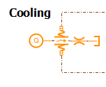
The cooling of the Nissan Leaf e-machine is composed of three channels of coolant inside the frame. The frame has been divided into two parts around the cooling jacket, one in contact with the yoke, the other one with ambient air, both being in contact with the end cap. Since the three channels are in series, the cooling loop is modeled with one component representing the total channel length. For the heat exchange coefficient between the liquid and the motor bloc, one can use either classical correlations for laminar and turbulent flow, or import heat exchange coefficients computed by a CFD tool, such as Simcenter STAR-CCM+.
Nissan Leaf e-machine cooling + 1D model (picture from [7])
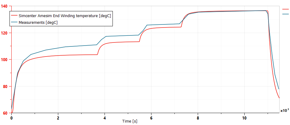
The transient scenario used for a model first validation is extracted from [5]. Comparison on the end winding temperature proves the validity of the approach.
Machine thermal model integration in vehicle
The battery electric vehicle model is shown hereunder. It is composed of a longitudinal vehicle model, a quasi-static battery model, an electric motor model and its control as well as a driver and a high-level controller.
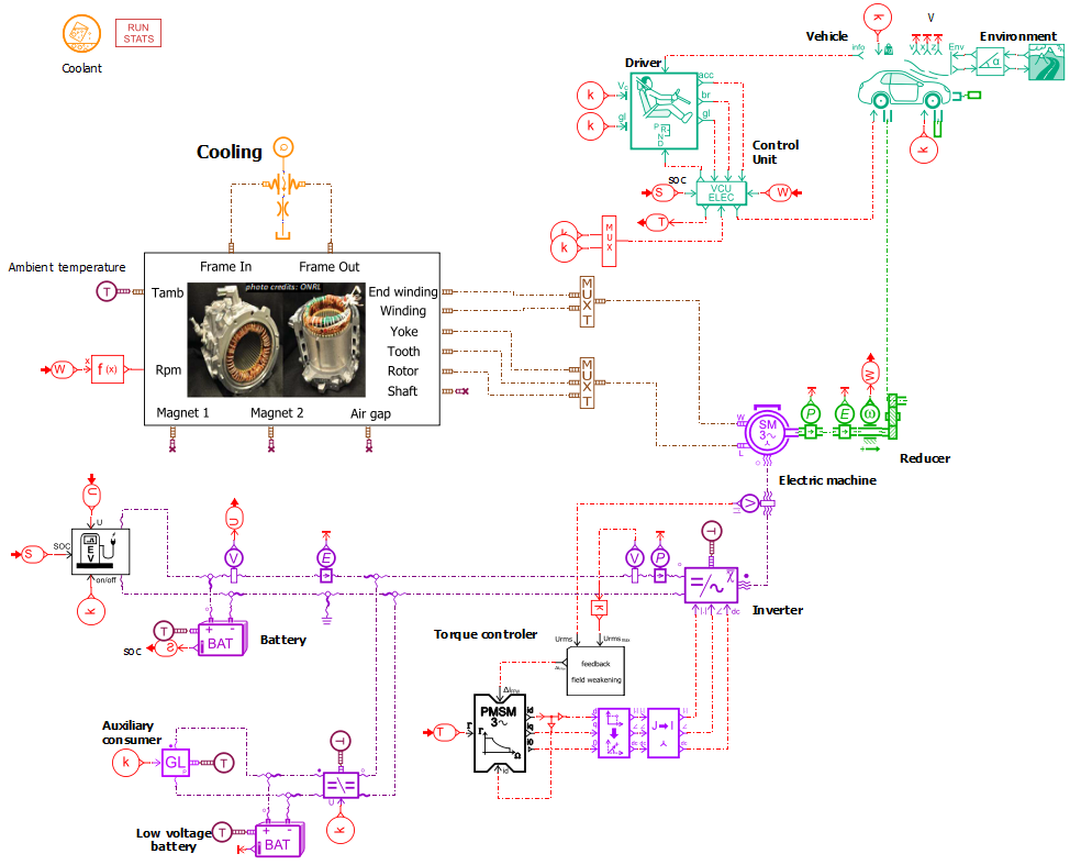
The e-motor model has been obtained by model reduction of a Simcenter SPEED representative model. This reduced model enables to simulate the machine electromagnetic performance while taking into account:
- the magnetic non-linearities,
- the permanent magnet temperature,
- the losses in the rotor, yoke and tooth sectors,
- the winding temperature.
Similarly, to the machine flux linkage datafile, the machine total iron losses have been obtained from the Simcenter SPEED. The export from Simcenter SPEED has been realized 4 time for 4 different magnet temperatures. These iron losses have been divided in 3 different datafiles according to 3 different sectors: the yoke losses (iron losses), the tooth losses (iron losses) and the rotor losses (iron losses + magnet losses).
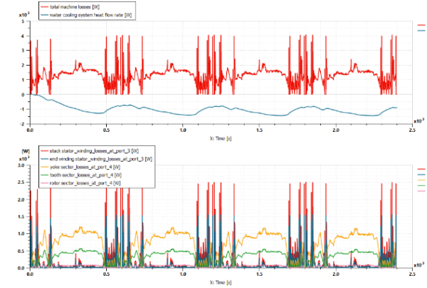
The vehicle mission is the SFTP-US06 driving cycle, repeated 4 times. Just as an indication, these 4 cycles correspond to 40 minutes of driving, but the simulation time is only 1 minute.
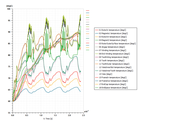
As a result of the thermal simulation of the electric machine, you can see on the left the total machine losses as well as the losses on each sector such as yoke, rotor or winding. On the right, you can see the temperature at each thermal node. Then you can check if these temperatures remain under the limit you have defined to ensure machine reliability and performance.
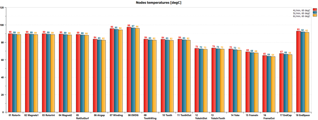
Hereunder you can find the result of an analysis done by changing the maximum flow rate delivered by the pump, between 4L/min and 6 L/min. Rapidly, the impact of the pump flow rate on the motor temperature can be assess.
Conclusion
In this demo example, we emphasize how an electric powertrain with a detailed thermal model can be used to both validate:
- the electric powertrain electromechanical performance and efficiency.
- the machine thermal behavior in realistic vehicle conditions.
Going further
This level of detail for the electric drive subsystem is well suited for more thermal simulation and validation. For instance, you can:
- integrate detailed bearing and windage models for more predictive powertrain efficiency. The resulting losses should be added to the machine thermal model.
- include a proximity losses model for the winding resistance in the PMSM submodel.
- validate the design of the cooling of the machine.
- validate the global electric vehicle energy management by including a thermal model of the battery and inverter with the associated cooling systems.
There is also the possibility to parametrize an electric machine thermal model starting for Simcenter SPEED. Watch this video to learn how:
In addition, you can read this blog to learn how to export from Simcenter Motorsolve the electromagnetic performance of an e-motor to Simcenter Amesim.
Author: Lionel Broglia
Reference
- Bjorn Andersson, “Lumped Parameter Thermal Modelling of Electric Machines”, Chalmers University of Technology, 2013,
- Gabriele Luca Basso, “Improved Thermal Models for Predicting End Winding Heat Transfer”, KTH Royal Institute of Technology, 2013,
- S. Touhami, “Lumped parameter thermal model of permanent magnet synchronous machines”, LAPLACE, CNRS, University of Toulouse, ENSMA, 2017,
- A. Boglietti & A. Cavagnino, “Analysis of the Endwinding Cooling Effects in TEFC Induction Motors”, IEEE transactions on industry applications VOL. 43 NO. 5, 2007,
- Giuseppe Volpe, “Reverse engineering of an electric vehicle motor and tests of a charging station”, Universita degli Studi di Cassino e del Lazio Meridionale, 2014,
- Rong Yan, “Electrified Vehicle Traction Machine Design with manufacturing considerations”, McMaster University, 2016,
- Dr David Staton, Dr James Goss, “Open Source Electric Motor Models for Commercial EV & Hybrid Traction Motors”, Motor Design Limited – CWIEME Berlin, 2017