Design space exploration for aircraft systems with Simcenter

To help you efficiently handle design space exploration for aircraft mechanical systems, Siemens comes with an innovative approach based on Simcenter solutions.
Over the years, scientists and engineers have discovered many paths that can lead to better aircraft. However, highly interconnected system architectures increase the complexity and slow down the pace of innovation. Moreover, multiple dependencies and constraints between components (such as joints and limitations on available space) make the design of mechanical systems even more complex.
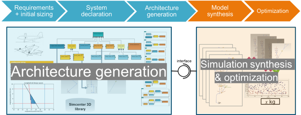
The new Siemens methodology for design space exploration consists of two main parts: architecture generation and simulation synthesis (Figure 1).
System architecture generation
Usually, a new design begins with a brainstorm session or a sketch, which is a mental model that is put on paper in the form of a diagram. This is called the system topology or architecture. It describes from which components the system will be built and how the components interact with each other. The system topology can have a large influence on the overall performance of the system. Therefore, Siemens developed a new methodology for automatic system architecture generation [1].
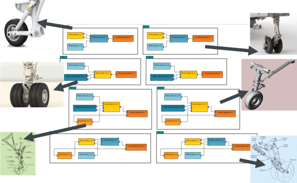
The user only needs to provide a formal description of the components that make up the system, and how they interact. Then, an advanced mathematical solver finds all possible system topologies. In summary, the first part of the methodology is to automatically generate all possible architectures for a user-defined set of components (Figure 2).
Simulation synthesis and simulation workflow generation
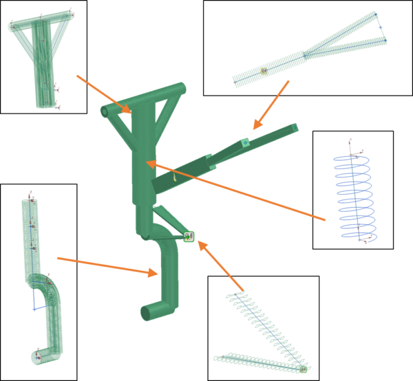
The second part of our approach enables engineers to automatically synthesize simulation models in Simcenter 3D and generate simulation workflows based on requested outputs. The synthesis is based on template simulation models that represent the components of the system that is described by the topology. We created a library of template models, which includes simplified and detailed parametric CAD models, Finite Element (FE) models and multi-body (MB) simulation models in Simcenter 3D. Figure 3 visualizes the synthesis of an FE assembly by using template FE models for the individual components.
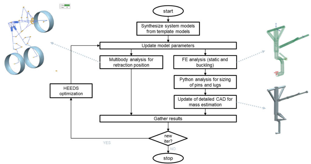
The workflows have been integrated with an optimization process in HEEDS to perform the sizing of the mechanism for a given set of load cases and constraints. In addition to the CAD, FE analyses and MB simulations, analytical methods written in Python have been added to the workflow. Consequently, the developed simulation synthesis methodology leads to a streamlined design process in which many repetitive and non-creative tasks are automated while increasing the reuse of knowledge and models [2].
Landing gear use case
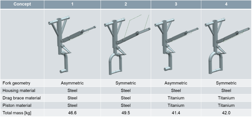
Let’s demonstrate this on the preliminary design of a nose landing gear. The use case was provided by GKN Aerospace. The methodology helped to generate and optimize variants of a nose landing gear with different piston geometries and materials. Moreover, we generated a complex workflow that is composed of a static MB simulation, static FE analyses, an analytical method for the sizing of the pin-lug connections and updating of CAD models for mass estimations (Figure 4). Subsequently, the SHERPA algorithm of HEEDS and a local optimization algorithm have been used to minimize the weight of each variant (see the results in Table 1).
Summary
This design space exploration methodology enables:
- automatic architecture generation
- automatic simulation synthesis of simulation models
- automatic workflow generation.
This is possible for CAD, FE analysis and MB simulation models in Simcenter 3D. You can handle the exploration of a large design space of alternative system topologies, while reducing lead time. In collaboration with GKN Aerospace, we studied a nose landing gear use case. The methodology is versatile, and it can be applied to any mechanical system. Thanks to the knowledge gained on landing gear design, the next step is to implement that methodology in a vertical application for Simcenter 3D dedicated to preliminary landing gear design.
Acknowledgements
The authors gratefully acknowledge Flanders Make and VLAIO (Flemish government agency Flanders Innovation & Entrepreneurship) for their support of the ICON project HBC.2016.0460 CONCEVAL (Multi-Attribute Concept Evaluation of Lightweight Structures). The project was coordinated by Flanders Make, with industrial partners Siemens (Siemens Digital Industries Software, Belgium), Tenneco, Bosal, Lambrecht and Noesis Solutions, and with industrial use case provider GKN Aerospace.
References
- [1] Menu J. & Nicolai M. (2017), “A methodology for automated design, verification and simulation of electrical power systems for aircraft”. in International workshop on aircraft system technologies, Hamburg, Germany.
- [2] Allegaert E., Menu J., Lemmens Y., Dutré S., Ongut E. & Wilson W. (2020), “Architecture-based conceptual design for mechanical systems applied to landing gear”. 1st Edition of the Aerospace Europe Conference, Bordeaux, France.
Interested in exploring more on landing gear design? We invite you to read:
- On-demand webinar: Design safe and reliable landing gear ready for future aircraft configurations
- Blog: Design safe and reliable landing gear ready for future aircraft configurations
- GKN Aerospace Fokker Landing Gear case study: Landing gear manufacturer uses Simcenter software to design safe, high-performance products
- Safran Landing Systems case study: Accurately predicting landing system performance with system simulation


