Before you google ‘component-based transfer path analysis wiki’
Would you google ‘component-based transfer path analysis wiki’? Perhaps, you know what transfer path analysis (TPA) is, but ‘component-based TPA’? How to read this term? What is it? Are you curious? Well, then you are at the right place. Let me start from the beginning.
During my commute to work, I usually spend quite some time in my car, not only because of the great distance between my home and the office but also because of the endless traffic jams around Brussels. And during this time, as an engineer, I tend to listen to the sound and vibrations of my car. Although I drive a good hybrid car, I still notice certain annoying high frequencies, when the car accelerates, or seat vibrations, when it brakes or slows down. When I tried to find out the cause and how it propagates from the source to my ears and body, I realized pretty quickly that this is not so obvious.
For car builders, the challenge of defining the noise and vibration source in a vehicle is of course even greater. Automotive car builders strive to meet the comfort expectations of their customers. Meanwhile, they increase the number of car variants and work against the clock to bring new models to the market as quickly as possible. Fortunately, there are innovative technologies that help automotive engineers to develop the best cars, despite the pressure to minimize costs and time to market.
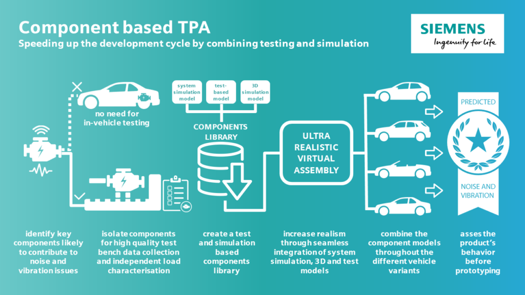
One of these technologies is component-based TPA. Using the same principles as transfer path analysis, it grabs the attention of noise & vibration engineers in the automotive industry. It is a very promising technology as it helps to predict and assess vibroacoustic performance upfront. Indeed, it uses vehicle virtual prototypes, instead of validating and testing the physical prototypes.
What exactly is component-based transfer path analysis?
Component-based TPA is a powerful methodology to predict the NVH performance of active components (also referred to as sources) in a virtual vehicle environment. It allows independent source characterization of the active components with blocked forces and enables full-vehicle level NVH predictions by virtually creating vehicle or system assemblies using Frequency Based Sub-structuring techniques (FBS). These blocked forces are typically obtained using TPA techniques on a component test bench or even on a test vehicle. FBS allows coupling numerical substructure models to experimentally obtained models, for example, a rigid body model of an HVAC compressor, FEM models for structural components, such as suspension, and experimentally obtained models for mounts and vehicle body. This allows a quick assessment of a large number of design variants and permanent pro-active control of the NVH performance.
To extend the component-based transfer path analysis wiki answer
Application case: electric motors
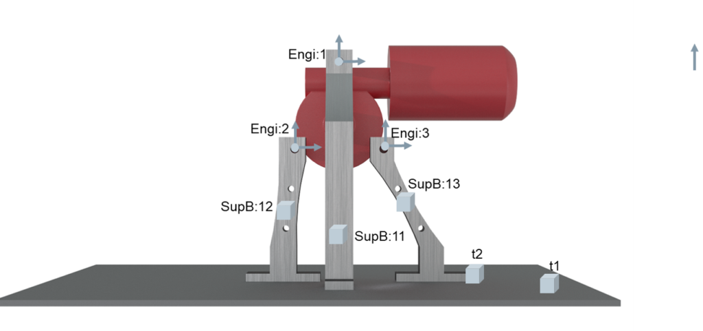
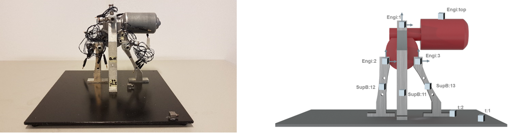
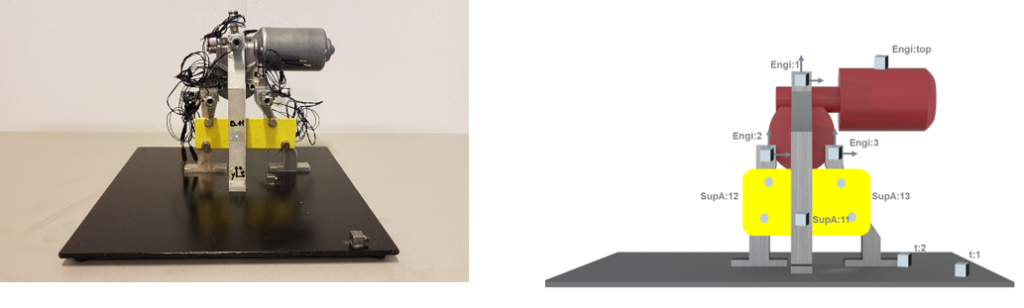
As an example, I will explain the principle of component-based TPA using Simcenter Testlab, based on a wiper electric motor demonstrator. Firstly, we connect the electric motor to a metal support frame consisting of three metal brackets (see picture below).
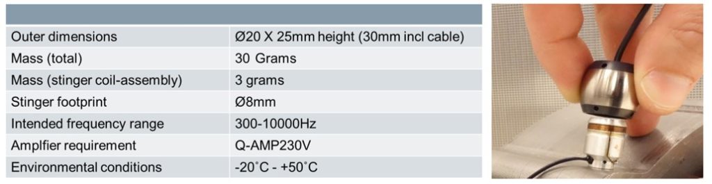
We already measured the necessary Frequency Response Functions (FRF) and Noise Transfer Functions (NTF) data using the Simcenter Testlab MIMO FRF Testing functionality and QSource High-Frequency Shaker (Q-HSH). The shaker enables structural/vibroacoustic FRF measurements in the high-frequency range (300Hz-10kHz). This is very useful for electrical components or electrified powertrains.
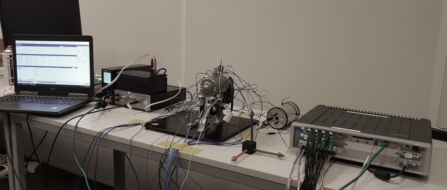
For operational measurements, we have measured engine run-ups from 300rpm to 3000rpm using Simcenter Testlab Signature Acquisition and the Simcenter SCADAS acquisition system.
The three main steps:
Source Characterization
Target Assembly
Performance assessment
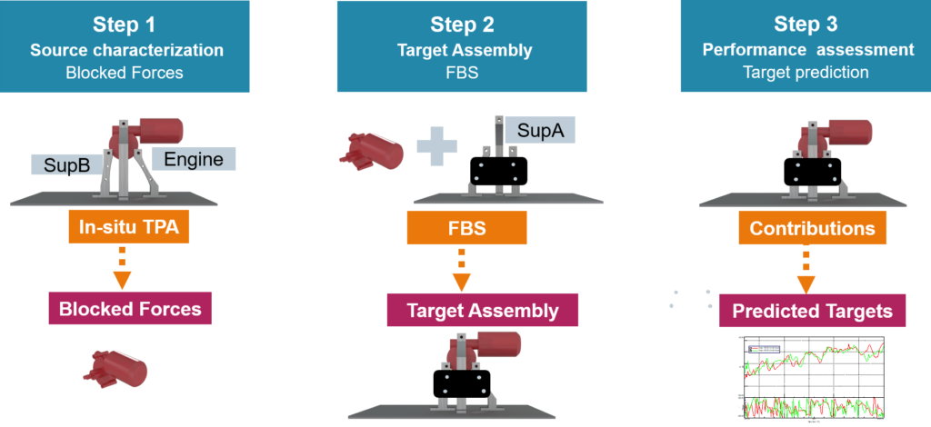
Step #1: Source Characterization
To characterize the source with ‘blocked forces‘, we will use the so-called in-situ TPA method. This means that we use an existing physical assembly also called the original assembly of the source and a receiver to determine through matrix inversion the forces at the connection points in the coupled conditions. See below a picture of the original assembly. These forces correspond to the ‘blocked forces‘. The process is shown next in the video.
Step #2: Target Assembly
Secondly, we will now virtually couple the same source with a new receiver to build the target assembly (see picture below). The new receiver has compared to the original receiver an additional metal plate connecting the two outer legs of the support frame adding stiffness and changing the dynamics of the original receiver. We use the FRF-based substructuring technique for calculating the FRFs of the target assembly. The next video shows the process.
Step #3: Performance assessment
Finally, we will assess the performance of the source in the new assembly virtually without the need for any physical coupling. The next video shows how easy and fast it is to examine the new target assembly performance in multiple dimensions using comprehensive 4D displays such as contributions plots and vector displays. It allows to investigate the contribution of each path in detail and to detect problematic operational forces or transfers. This helps engineers to optimize the product design early in the development stage without the need to wait for the availability of the physical prototype.
So, why should you start considering component-based TPA?
Maybe one day you will apply this fantastic technology to make my daily traffic jams more enjoyable?
I think the benefits and gains of this technology are quite obvious. It allows predicting the NVH performance of each variant and load case even before the first prototype is available. It enables the early detection of potential NVH issues and system optimization at a stage where the impact and cost of modifications are still minimal.
Would you like to explore this technology in depth? Do you want to go beyond the ‘component-based transfer path analysis wiki’ answer?
Register for the on-demand webinar and discover all the possibilities this technology can bring to you.