Hydrogen fuel cell modeling: (almost) all you need to know
The discovery of atoms is a story of fights and religions, of progress and dark ages, of opinions against physical evidence. Looking back it is hard to believe that such a fight ultimately lead to things like a hydrogen fuel cell. But first things first: Almost 2400 years ago, in Greece, Leucippus and Democritus understood that the macroscopic characteristics of a material depend on the infinitely small structures which the material is made of. Leucippus and Democritus coined the word “Atom”, which means uncuttable. But it was only at the end of the 17th century, after almost 2000 years, that such findings were finally accepted, finding the support of remarkable scientists such as Sr. Isaac Newton and Robert Boyle.
Famous atoms
Let’s talk first about some famous atoms. Uranium has an atomic number of 92, meaning 92 protons in the nucleus and 92 electrons spinning around. What we exploit in nuclear powerplants are its isotopes, atoms with a different number of neutrons in the nucleus. Such atoms are unstable and release energy through radiation that can be exploited for several purposes. A slightly smaller atom, with an atomic number of 78, is platinum. Platinum is a real champion in the automotive industry for its catalytic properties. It has a very high melting point, which makes it very thermally durable, it gets poisoned by sulphur composites only at the surface and it can be easily recycled.
The small but famous atom
But the main topic of this blog is the hydrogen atom. Hydrogen has an atomic number of 1, meaning that it is made of only one proton and one electron. Such simplicity makes it suitable to bond very easily with oxygen. In other words, a chemist would say that it is extremely reactive whilst an engineer would say that it is…explosive. It is 8 times smaller than an atom of uranium: it is so tiny that it can diffuse through solid material. It is for sure one of the most abundant elements on the planet, but because it bonds extremely easily, we can rarely find it in its pure form.
The challenge of producing hydrogen
How do we produce hydrogen then? 95% of hydrogen is produced by steam methane reforming (SMR). We basically take a very nice gas such as methane, we make it react with water in a catalyst and we obtain hydrogen and CO2. A lot of CO2… Since the CO2 is obtained pure, it can be stored in some underground sites (Carbon Capture and Storage), which is quite an expensive and early-stage technology.
The second way we can produce hydrogen is by electrolysis, a process that we can assimilate to an inverted fuel cell. The problem is that hydrogen and oxygen react spontaneously together to produce water.
If you are reading this blog, it is very likely that you are an engineer. And if you are an engineer, you know that inverting a spontaneous process requires energy. And this is exactly the case for electrolysis. It is an extremely energy-consuming process and 1 kg of H2 produced by electrolysis is more expensive than 1 kg produced with SMR.
To make things worse, it is difficult to store hydrogen. Very recently, an explosion in a stocking site in South Korea made South Koreans start wondering about the safety of such technology . Also, an atom of hydrogen is very tiny, right? Well, since it can easily diffuse through solid material, hydrogen tanks must be very carefully built and are therefore very expensive.
Advantages can outweigh disadvantages
I am aware that I paint a terrible picture of hydrogen. So why is this technology gaining such traction? Three main reasons: the first one is diversification of the energy portfolio. When a country does not have suitable territory for wind and solar, hydrogen can be a viable solution to decarbonize the energy portfolio. Second reason, hydrogen seems to be suitable for long distance transport such as trucks and trains. And final reason, it offers much faster refueling compared with batteries. It is true that fast-charging batteries and recharging spots will eventually appear on the market, but these would also place a very high demand on power networks, which might not be possible with existing infrastructure.
But how does a hydrogen fuel cell work?
In the automotive sector, we can use hydrogen fuel cells to power cars. First things first, what is a fuel cell? A hydrogen fuel cell is an electrochemical cell able to produce electric current via the reaction of hydrogen with oxygen and releasing only water as a result (yes, you got it right, only water).
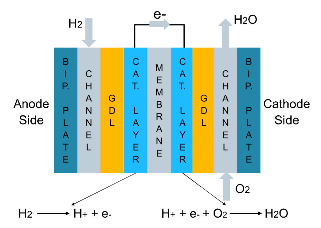
A fuel cell has two sides (Fig. 1). At the anode side, a channel feeding hydrogen is interfaced to a bipolar plate (generally made of graphite). The hydrogen then diffuses through a highly porous layer, called gas diffusion layer (GDL), which is interfaced to a very thin catalytic layer in which platinum promotes a reaction that splits hydrogen into H+ and one electron. Notice that platinum usage is one of the reasons for the high cost of fuel cells. Another fundamental part of the fuel cell is the membrane, which lets only the H+ pass through, whilst the electrons need to bypass the membrane and are gathered externally, producing the current. Finally, at the cathode side in a second catalytic layer, H+, the electrons and the O2 fed by the cathode channel recombine to produce gaseous water.
We find two main problems with fuel cells. The first one is flooding, meaning too much liquid water produced at the cathode side, leading to inefficient feeding of the reactants towards the membrane. The second problem is drying out of the membrane, when the membrane humidification level is not enough, which can lead to severe damages.
How do we model a hydrogen fuel cell in 3D?
The strategy we follow for a hydrogen fuel cell in Simcenter STAR-CCM+ is to model the real geometry in 3D, by calculating a transport equation for momentum, energy and flow. The interaction between the liquid and gas phase is also accounted for. A necessary evil for every CFD blog or presentation, is the modeling part in which the writer or the presenter lists dozens of equations. I’ll refrain from doing so, but let me at least describe the general strategy:
- the flow equation is modeled for the channels, with the wall interaction modeled as no-slip. It is necessary to capture this level of geometrical detail because the pressure drop calculation in such tiny channels plays a fundamental role;
- the flow equation is also calculated for the gas diffusion layers. Remember that in a fuel cell we produce liquid water which interacts with the gas transported at both the anode and cathode sides. Calculating such interaction with a Volume of Fluid (VOF) approach in a porous media is complex. Therefore, we use the Mixture Multi Phase (MMP) approach, which mimics the surface interaction between the two phases in a porous medium;
- the bipolar plates are modeled as a solid, in which electric current is conducted and the solid can absorb part of the ohmic heating. The membrane is also considered as a solid, but it transports the solid ions and absorbs part of the electrochemical heating from the reactions. Talking about reactions, in our model they occur at the interface between the gas diffusion layers and the membrane, which is considered as infinitely thin.
Simulating hydrogen fuel cells

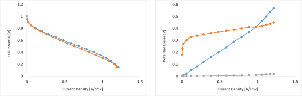
In order to showcase the model, two different geometries, FC1 and FC2, were simulated (Fig. 2). Both represent a portion of a single layer cell with wavy channels and FC2 is fed with double the amount of the reactants. The polarization curves for both configurations is shown in Fig. 3. Polarization curves are useful to compare fuel cells independently from their geometry:
the voltage is shown as a function of the surface-specific electric current density, showing the capacity of a given fuel cell to accumulate current at the bipolar plate surfaces. For instance, these two configurations show very similar polarization curves, but we will see that they have fundamentally different dynamics. In a polarization curve, there are several types of losses that occur. At high voltages, we only have activation losses, in which reactions are very slow and the cell barely produces any useful electricity. After this phase, ohmic losses due to the internal resistance of the cell start growing linearly. At high current densities, the cell works at extreme conditions. Here, concentration losses start growing. Reactants are consumed more and more but eventually they are not fed quickly enough to the catalytic layer, leading to efficiency loss.
Understanding how the hydrogen is consumed is fundamental
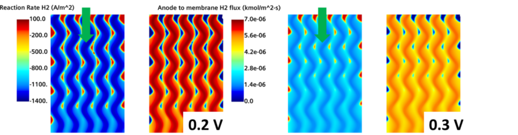
The first thing you need to think about when analyzing a hydrogen fuel cell is how the hydrogen is being consumed. Fig. 4 represents the H2 reaction rate, where dark blue regions represent the highest hydrogen consumption. In the same figure, the H2 flux towards the membrane at the anode side is shown. Dark red regions represent the parts in which the hydrogen is rapidly fed at the interface between the GDL and the membrane.
Although it doesn’t look like the most interesting image, it reveals a lot about the physics of a fuel cell. Remember that this image is taken at the Anode GDL/Membrane interface. The hydrogen has already diffused from the channels and all the way through the GDL and is finally ready to react at the interface with the membrane. Yet the gradients are still very well defined – meaning that, in the GDL, hydrogen is not homogeneously distributed at the membrane.
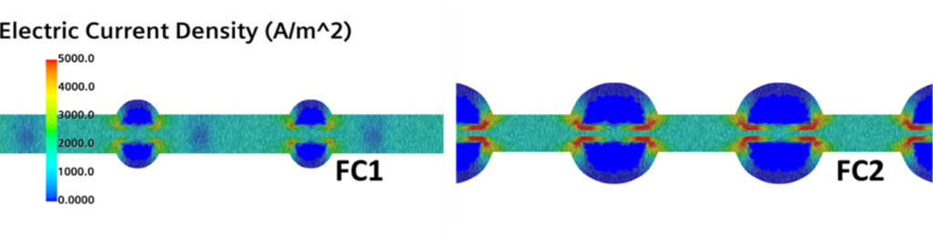
Current gradients and water production lead to durability and efficiency problems
Is this a problem? Oh yeah.. Let’s now compare the electric current density fields for the two geometries in Fig. 5. Where the red gradients are shown, a higher quantity of electricity is produced, and this happens at the corners of the channels. Remember that this is where we have the higher concentration of hydrogen and, on top of that, where the bipolar plates are directly interfaced with the channels. In other words, this is the point in which the bipolar plates gather more current and those gradients are certainly not helping the temperature distribution and the durability of the cell. FC2, for which double the amount of reactant mass is provided, might indeed have a shorter life than FC1.
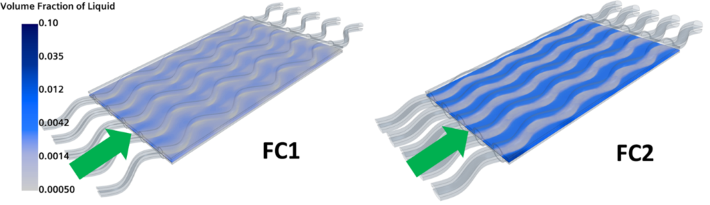
Furthermore, one of the benefits of fuel cells is the fact that only liquid water is released in the atmosphere. Ironically, water is actually a fuel cell designer’s worst nightmare. At high current densities, water is produced at the cathode interface and it interrupts the correct feeding of the reactants. The volume fraction for the two configurations is shown in Fig. 7. And yes, FC2 produces much more water than FC1, suggesting that it would be a less efficient configuration. So, although they have similar polarization curves, FC2 is subjected to more extreme conditions that might lead to inefficiencies and shorter life.
A few final words
So, in summary, designing a hydrogen fuel cell is indeed not easy. Feeding more hydrogen to the system will lead to stiff gradients, non-homogeneous temperatures and higher production of water. But at the same time, we might need more current from our system: as for any engineering system, there are many trade-offs for fuel cell designs and Simcenter STAR-CCM+ can be your best ally.
I want to finish with one last question. Why are we not simply burning hydrogen in an internal combustion engine (ICE)? The main reason is that the efficiency of a fuel cell is almost double that of an ICE (efficiency to the wheels). Of course, we might argue that the ICE is a well-known and highly-developed technology whilst fuel cells still need some R&D. Another challenge is that H2 has a relatively low volumetric energy density. Fueling an ICE with H2 would require double the tank volume for the same driving range, and this would require quite a large tank installed in a passenger car.