Discover the latest acoustics modeling technique: HVAC noise propagation with porous and absorbing materials
Yippee-ki-yay it’s HVACs
The acoustics of your HVACs (Heating, Ventilation, and Air Conditioning) piping will not give you improved downforce or make your car more slippery on the straights. Despite this, you will appreciate it when an aerodynamics expert optimizes your HVAC’s aerodynamics. This statement is especially true if you drive an electric vehicle and your cabin is filled with nothing more than blissful silence or optimized to hear your favorite tunes in full surround sound. Quite clearly, there is more to an HVAC duct than a personal transit system for Bruce Willis at Christmas.
How do HVACs ruin your ambiance?
Passing air through and over surfaces inevitably creates fluctuations in the flow and forces on the surfaces. These, in turn, have the potential to create noise. Since the air supply is coming from a constant location, namely the fan, this noise will tend to be repetitive and annoying in an otherwise quiet environment.
When an engineer considers the cabin environment, the sound is critical to the overall experience. Since no one wants to spend prolonged periods of time within the periphery of an annoying noise. However, some noises are difficult to predict or remove completely. Therefore, engineers model the soundscape of the vehicle digitally, so they can identify annoying noises and eliminate or modify them long before the first piece of sheet metal is stamped in a factory. To do this, in the case of the HVAC, they consider three environments.
Environment one: inside the duct
The flow field inside the ducting system can be complex due to components such as elbows, vanes, and flaps. The separation of flow and interaction of the disturbances with such downstream components are responsible for the noise source generated in HVAC ducts. The flow in this section is not affected by the downstream environment and therefore it can be modeled independently in an anechoic chamber or with the HVAC duct attached to a cabin. An engineer at an OEM may do these calculations. However, it is also possible that the ducts are a supplied part and the part supplier does the simulations.
Environment two: proximity to the outlet
As the air passes through the outlet, over any guiding fins, and suddenly finds itself in a vastly expanded space, there is the potential for turbulence and sound generation. Since this is a fascinating area for both the acoustics expert and aerodynamicist, it is modeled on its own.
Environment three: most of the car’s interior
We will consider environment one from your ear to the near proximity of the HVAC duct outlet. Easy you may think, a simple sound wave happily travels along from the outlet until your eardrum conveniently gets in its way. This may be true in an anechoic chamber, but in this case, you are in a car. Other sound waves interfere with our HVAC wave, and soft surfaces, such as seats, absorb sound, while hard surfaces reflect it. If these reflections are synchronized with the initial wave they will amplify it, however, if their waveform is shifted they will dampen the original sound. These are all considerations the engineer will need to consider if they want to understand what you will hear in the final production car.
Since the three environments will require different techniques and possibly different engineers to work on them, we will look at them in three steps.
Step 1: Computing the aeroacoustics field in the HVAC duct
The aerodynamics of the HVAC duct system, together with the aeroacoustics source generation and near field propagation from the HVAC duct outlet, is computed in Simcenter STAR-CCM+. This can be done for an isolated HVAC duct that is not attached to the car cabin. When solving this way, the effect of the cabin can be ignored in the acoustic propagation. A time domain solution with Large Eddy Simulation (LES), and Perturbed Convection Wave Equation (PCWE) can be used for this calculation.
This simplifies the noise source computation since the cabin domain doesn’t need to be added to the flow calculation (possibly resulting in a smaller flow domain). More importantly, the cabin acoustic properties, such as absorbing surfaces and porous domain can be better defined in a frequency domain solution, whereas the flow and near-field acoustics is calculated in the time domain.
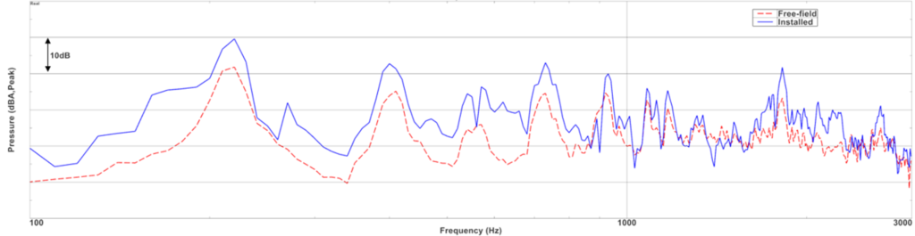
This solution can also give the acoustic response at observer locations in free-field without the cabin, simulating an environment akin to the HVAC duct being positioned in an anechoic room instead of the car cabin.
“Step 1” is common in various workflows and is beneficial for HVAC manufacturers who do not have access to the car cabin model. However, for the OEMs who can also include the cabin in the acoustic domain, a hybrid solution can be considered. Using the same source domain calculations, this hybrid solution doesn’t need to add extensively to the overhead of ‘step 1’ and will provide the flow information.
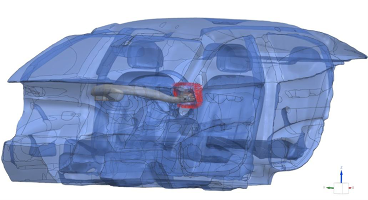
Step 2: Transfer the acoustic field on permeable HVAC duct outlet
Using the very same Simcenter STAR-CCM+ PCWE solution, CFD users can export the transient noise source components. In previous applications, transient aerodynamic output was requested either in rigid boundaries, like the HVAC duct surface, or the HVAC “volume” domain. However, since PCWE already solved the aeroacoustic near-field propagation in this application, at least until the HVAC duct outlet, we can export acoustic quantities directly from this simulation instead of larger aerodynamic quantities. These include both the acoustic pressure and velocity, which will be used in the next acoustic radiation calculation for the cabin. These quantities can be exported on a convex mesh covering the HVAC outlet that would fit in the car cabin, like how it would radiate in practice. The data format can be “.cgns” which is binary. The usage of such binary data export on a small permeable surface also reduces the data transfer between the CFD user and the Acoustic user (if different).
The time-domain “.cgns” files can be imported to Simcenter 3D in Model and Load Pre-processing. They can be converted to frequency-domain components. The resulting frequency domain permeable surface will be used as acoustic loads in “Step 3”.
Step 3: Compute the propagation in the cabin with the permeable loads
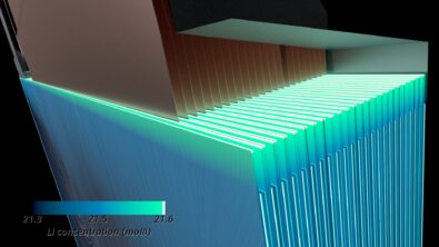
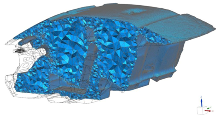
The cabin acoustic model where the HVAC duct will later be installed can be generated separately with separate mesh considerations. This is possible since the acoustic cabin model doesn’t have any flow-related meshing constraints. For standard FEM solutions, 6-acoustic element per wavelength requirement would already be coarser than the CFD mesh. Additionally, using the FEMAO, the cabin model can be coarsened in the volume since FEMAO lets the acoustic problem with coarse elements be solved by adapting element orders per frequency. A mesh similar to the one below can be used where very coarse elements can be used. This accelerates the solution time for lower frequencies.
The acoustic model can include absorber boundary conditions on the surfaces representing the roof, carpet, and door panels. The seats can also be defined as porous material. In case different acoustic domains, such as cabin air and porous seats, are needed in the same simulation solution, they need to be connected with “Acoustic Continuity” Simulation Object in Simcenter 3D.
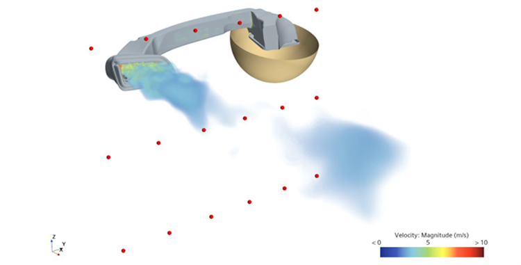
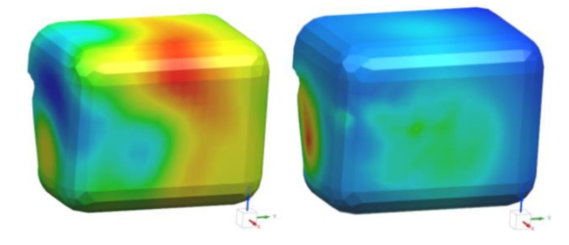
Including the absorbing and porous domains, one can solve the HVAC cabin noise with the permeable radiating surface acoustic loads. Animations show the effects cabin in propagation for one of the frequencies of interest. It is clear that neglecting the cabin effects in acoustic propagation (left) the acoustic waves radiate freely in the medium. However, including the cabin properties, the acoustic radiation is more complex since it now includes reflection and absorption.
Past research shows that hybrid methods where acoustic and flow are solved separately can provide more representative results than other reference solutions. Using such techniques, we can see that in the regions where we would expect the driver’s ear, the installed condition can provide acoustic levels which are more than 10dB. Therefore, once installed, including the cabin properties in propagation can make a significant difference to the HVAC noise prediction.
Simcenter 3D now also supports models with heterogeneous fluid domains. This means that the seats and other absorbing surfaces can be modeled as heavy air or a real porous material, while the rest of the cabin is modeled with regular air fluid elements.
Summary
The proposed coupling of flow and acoustics provides a solution to HVAC cabin noise problem with optimized source modeling and data transfer while keeping the flow and acoustics persona on their own platform. The cabin properties can be taken into account efficiently without increasing the overhead of the CFD solution.