Accomplish more by customizing Material Models with the New User-Defined Subroutines in C++
Create your own material model
One of the key challenges in CAE simulations is accurately representing the complex behavior of real-world materials. This is especially important in multi-scale simulations, where the accuracy of the global-scale response relies on the precise mechanical representation of each micro-constituent and their interfaces. To meet the needs of users designing parts with complex microstructures or new advanced materials, Simcenter Multimech 2306 allows users to create their own material models through user-defined subroutines in C or C++.
Traditionally, engineers and researchers have struggled with issues related to modeling advanced materials. Standard material libraries often don’t cover the full spectrum of materials used across various industries and products, forcing engineers to compromise on material models and accept some degree of inaccuracy in the results. Furthermore, although most CAE tools support user-defined materials, not all of them support multi-scale simulations where some or all of the micro-constituents are assigned a custom material.
The support for custom user-defined materials in Simcenter Multimech provides a powerful solution to these challenges. User materials can be applied in most simulation types in Simcenter Multimech: global scale models of parts, virtual tests at the microstructural scale, or True Multiscale simulations.
First example: fatigue in adhesive joints
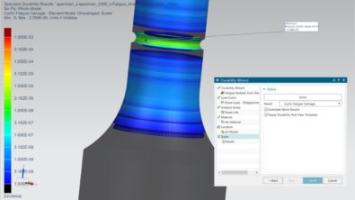
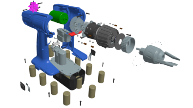
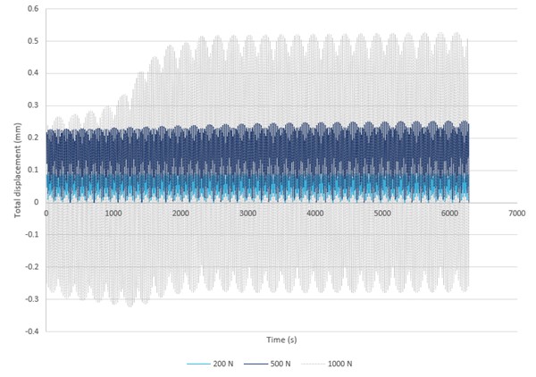
Adhesive materials often have a non-standard mechanical response compared to common engineering materials like metals. Moreover, their response can vary widely depending on the composition and conditions of use (humidity, temperature, etc.). Consequently, the simulation of models including this type of material serves as an excellent example of the power of using user-subroutines in Simcenter Multimech. In the example below, a joint is loaded under cyclic conditions with increasing load magnitude. A custom constitutive relation, tailored for modelling the adhesive behavior under fatigue, was coded and assigned to the adhesive elements. The results demonstrate the ability of the subroutine to capture the different fatigue responses in each condition, and to identify which zones of the adhesive domain are more prone to fatigue failure.
Second example: custom failure model with gradual stiffness reduction
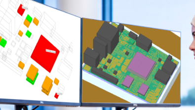
The example above showcases a single-scale use of the new feature, as no microstructural features have been modeled. In other words, the full model is on the scale of the components and the adhesive joint. However, user-defined subroutines can also be applied in multi-scale analyses, to model the response of specific micro-constituents. A powerful example of this new feature in a multi-scale simulation is the creation of a user-defined failure criterion. A common application for failure criteria in CAE simulations is to reproduce phenomena like fracture, cracking, or debonding, by reducing the stiffness of elements to almost zero if a specific criterion is met. In this case, the path of the reduced-stiffness elements represents the fracture path.
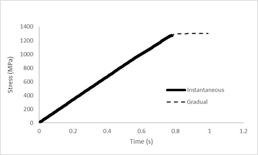
Although failure models exist in most CAE tools and have been used for decades, convergence is a common challenge: the abrupt reduction of stiffness can lead to higher residuals, requiring careful selection of mesh, time step strategy, stabilization, etc. To address this issue, users can develop a failure model in which the stiffness is not immediately reduced, but instead gradually decreased over several time steps. The picture and animation below demonstrate how the gradual stiffness decrease takes place:
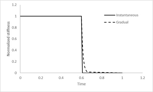
The result of the custom failure criteria in an actual multi-scale simulation is an improvement in the convergence of the non-linear analysis, leading to the simulation progressing much further than using a simplified failure model. The extended results allow users to perform post-failure investigations, showing how the component under investigation behaves after each localized failure mechanism takes place.
Unlimited possibilities with your own material models
The examples shared above demonstrate just a fraction of the potential that can be unlocked by customizing material models in Simcenter Multimech. Other examples of applications include:
• Temperature and strain-rate dependency in metals
• Custom multi-axial damage and failure models
• Low-cycle fatigue in microstructural components
• Mechanical response of unusual materials like glass, sand, cardboard, wood, etc.
Moreover, with regards to multi-scale simulations, material subroutines in Simcenter Multimech can be used at a microstructural scale, coupled with global scale models solved from Simcenter 3D in different solvers, like Nastran, Samcef, Abaqus or Ansys. This means that it’s now possible to code material subroutines that work with any of these solvers in C++, instead of their native Fortran programming.
For users struggling to meet expectations due to material complexity and inaccuracies caused by incorrect material modelling, user-defined models in Simcenter Multimech are a tangible solution. Comprehensive guidance and examples of code, compilation and usage are provided in the Simcenter Multimech documentation.
Simcenter Mechanical 2306
Simcenter Multimech is part of the Simcenter Mechanical group of Simcenter Simulation Software Solutions. This release of Simcenter Multimech was therefore part of the Simcenter Mechanical 2306 release, to find out more about this release read this blog.