Simcenter FLOEFD v18.0: What’s New? – Part 1

Simcenter FLOEFD v18.0: What’s New? – Part 1
Good news for the Simcenter FLOEFD user community: Simcenter FLOEFD v18.0 has been released, learn what great new features have been released in v18.0 and are available for immediate download.
Simcenter FLOEFD v18.0 features a wide range of new thermal management and productivity enhancement related functionalities to support the design engineer interested in using computational fluid dynamics (CFD) inside Siemens NX, Solid Edge, CATIA V5 and Creo. Let’s take a close look at them now:
New Battery Compact Models
The new battery compact model calculates the heat dissipation rate based on the electrical or electrical-chemical characteristics of battery cells. The two new models are:
- The Equivalent Circuit model: it represents a cell as a second-order resistor-capacitor (2RC) equivalent circuit model. The model inputs are OCV (open circuit voltage), resistance and capacitance values as functions of SOC and temperature.
- The Electrochemical-thermal coupled model: this model simulates thermal and electrochemical behaviors of the battery cell and requires the chemical properties of the electrolyte.
The heat dissipation rate should be applied to the cell in both models. The state of charge, voltage, current, and the temperature distribution can also be predicted (requires the Power Electrification module).
 Simulation of a liquid-cooled battery pack showing the cell temperature surface plot.
Increase Accuracy with Calibration
Since semiconductor package characteristics data used in the simulation can differ from the reality due to lack of knowledge about the internal structure, you can increase the accuracy of your data by using Simcenter T3STER. The market-leading thermal transient measurement system lets you obtain and use the true package internal structure and material properties to drive even more accurate simulation. In addition, the new Calibration mode in the Parametric Study functionality will search for package dimensions and material properties to fit the measured data (requires Simcenter T3STER Auto Calibration module and Simcenter T3STER hardware test equipment).
 The semiconductor package auto-calibration based on Simcenter T3STER measurements results in high-quality thermal models.
Flux Plot for New Insight
A great tool for getting insight into your design, the Flux plot shows the amount of heat going from one component to another (by conduction). The plot can also show heat transfer to the fluid via convection or radiation. In addition, you can group components to see the heat calculated for all grouped components. Lastly, refer to the pie chart to understand the balance of heat for incoming and outgoing heat.
 The flux plot is showing heat fluxes between various components and to the environment through convection and radiation.
Improved EDA Support
The disciplines of electrical and mechanical engineering are getting closer and closer so that engineers require a greater connection between their Electronic Design Automation (EDA) and Mechanical Design Automation (MDA) tools. With the latest release of Simcenter FLOEFD, the Simcenter EDA Bridge module now supports the IPC2581 (Rev B) and IDX (Prostep) formats. A new method to calculate effective thermal conductivity based on empirical data is also added (requires EDA Bridge module).
OneSim Co-Simulation
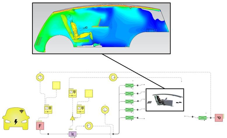
OneSim is a unique tightly coupled co-simulation workflow that enables a Simcenter FLOEFD model to be considered as part of a Simcenter Flomaster network. One or more Simcenter FLOEFD hydrodynamic boundary conditions are nominated for linking to the Simcenter Flomaster network. Once connected, a simulation instigated from within Simcenter Flomaster will solve both the FLOEFD model and the Simcenter Flomaster network concurrently, until the steady-state or transient convergence. Flow rates, pressures, and fluid temperatures will be communicated through the linked boundary conditions / hydraulic nodes throughout the solution process (requires Simcenter Flomaster v9.1 product).
 A OneSim co-simulation example of a car cabin HVAC simulation in Simcenter FLOEFD and its Simcenter Flomaster HVAC network model.
Post-processing:
- Creating cut plots or flow trajectories has been made more streamlined. You can create a cut plot normal to a curve. This new option makes creating a section along the centerline of a tube or circular channel easier. Surface parameters can now be calculated in a section place and not only on the geometry surfaces. Simply select a plane, planar face or curve to calculate local and integral parameters in the section. Also, cut plots and surface parameters can be linked to the location of the cut plot. If a section plane divides the model into several closed contours, parameters can be calculated separately for each contour. Flow trajectories can start from linear or rectangular virtual objects (not a CAD geometry) which you can interactively move, rotate and resize in the graphics area.
- The new custom visualization parameter enables the use of logical expressions such as IF, OR, AND etc. as well as larger than and less than. This enables the plot of only specific criteria or the surface area these criteria apply to.
Watch out for Part 2 of this post and for additional information and a complete list of new capabilities, please go to the Support Center site (https://support.mentor.com) or read the release highlights file provided with the installation package.


