6 Advanced Methodologies for Gear Test Rig: Part 1
Gears. Gears are used since the middle ages. Should be settled science by now, right? That’s about what I thought when I started. However, after discussing with colleagues and digging into the work of our research team, I recognized: Far from it! The current trend from Internal Combustion Engine towards electric motors reveal noise and vibration issues, which many companies in that industry do not have a solution for to this day. Part of them are originating in the gearboxes, and to solve them you need advanced simulation methods and high-end testing methods.
Siemens PLM Software is focusing on rotating machinery, gears and driveline, both from the test and simulation methods and tools perspective. Today’s post is the first of a two part blog post that gives you more insight in the high precision gear test rig, that we have built for the validation of advanced multi-body simulation methodologies, so we can increase the confidence in virtual prototyping based on real-life data.
1.) Context: NVH, need for light and complex gear geometries
Gears are key components of any mechanical systems containing transmissions and drivelines. Widely used in industrial applications, their range of application goes beyond automotive, marine and aerospace industry. The requirements and regulations on the noise and vibration levels (in terms of safety and comfort for the users and the environment) become restricted every year. As a result, current industrial needs are centered on higher power-to-weight ratios, robustness, power loss reductions and improved noise/vibration behavior of the transmission systems.
The prediction of gear characteristics using simulation tools can help to optimize designs and to significantly reduce production costs of gear transmissions. As the accuracy and robustness of numerical modeling techniques improve constantly, gears can be designed in their optimal operating configurations, leading to quieter power transmission systems. The quality of simulation tools is usually evaluated by experimental validation. The comparison of the vibration levels between numerical and experimental results is a good indicator of the modeling accuracy.

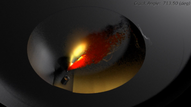
Figure 1: The mesh is adapted to the complex geometry of the lightweight gear, including three holes on the body. (Illustration made in Simcenter 3D)
2.) The Solution: Simcenter 3D
The Simcenter portfolio by Siemens PLM Software is all about combining the best of both worlds of Test and Simulation. Currently, the RTD team of Siemens PLM Software is very active to extend its Simcenter 3D offering to drivetrain and powertrain multi-body simulation. Siemens has a wide portfolio of gear multi-body simulation capabilities, ranging from fast screening methods to efficient and very accurate advanced analysis methods. Also, we have the capabilities and experience to validate our simulation methodologies for these and other complex mechanical engineering scenarios. Lastly, leveraging our Simcenter Engineering services department capacities.

Figure 2: The gear test rig is mounted on a large concrete base block. (Image credit: SISW)
3.) Zoom on the Advanced FE modeling techniques
The advanced FE preprocessor is the most accurate gear contact modeling methodology at Siemens. This method is based on a novel formulation, leveraging on model order reduction technologies, and therefore highly accurate as well as relatively efficient (see more information in the white paper). The pre-processing tool named FE preprocessor has been developed in a joint cooperation between the KU Leuven and the University of Calabria. The advanced FE preprocessor methodology allows the modeling of gear bodies with complex shapes. The capabilities have been extended to account for a wide range of flexibility-induced phenomena (lightweight gears, convective coupling effects, etc.).
4.) The Gear Test Rig: motivation, capabilities, and instrumentation
For the purpose of validating the accuracy of the gear multi-body simulation methodologies on the basis of experimental data, Siemens PLM Software, KU Leuven and the University of Calabria have designed a high precision gear test rig at the Siemens PLM Software premises in Leuven, Belgium. The main objective of the test rig activities is the assessment of typical gear-related physical quantities in static and dynamic conditions, under controlled operating conditions (torque, speed, center distance, misalignment). The test rig provides the possibility of heavily instrumenting a gear pair under controlled operating conditions. Recently, a lot of efforts have been dedicated to the application of strain gauges (both at tooth root and gear body) on lightweight gears. The gear test rig is used to experimentally investigate the response of the system while excited by a meshing gear pair. The test rig is presented in Figure 2. The different components of the test rig are illustrated in Figure 3.

Figure 3: Gear test rig three-dimensional representation.
5.) Cooperation context: RTD projects from which the Gear Test Rig originates
The gear test rig has been designed and manufactured in the framework of the EC Marie Curie project “DEMETRA” and the VLAIO project “ECO-Powertrain”. The Marie Curie project framework is dedicated to the recruitment of new staff members and the exchange of staff members between organizations, which has made the “DEMETRA” project a fertile ground for the exchange of technologies, ideas and personnel between the partners Siemens PLM Software, KU Leuven and coordinator University of Calabria (UNICAL), which have all been instrumental for the achievement of the gear test rig.
6.) Lightweight gears
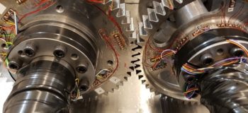
In a recent experimental campaign performed at Siemens, a pair of precisely manufactured gears have been tested using the in-house test rig. The lightweight gear has a thin rim and three holes in the body. On the other side, a solid gear is mounted with identical dimensions, but a slightly different microgeometry. Once the gears are fully instrumented, they are mounted on the test rig, to be analyzed in different operating conditions (torque, speed). The lightweight gear pair is shown in Figure 4, in a mounted configuration.

Figure 4: A pair of solid (left) and lightweight (right) gears are mounted in the test rig. The gears are instrumented with strain gages in the tooth root and on the body. (Image credit: SISW)
Join us next week for part 2 of Gear Test Rig which focuses on the type of measurements that are possible with test rig!