NX | Tips and Tricks | X-Form
In our latest NX™ software Tips and Tricks video, we explore how to use the X-Form command to edit surfaces or spline curves by dynamically manipulating pole locations. This tool excels in advanced shape design, enabling quick and efficient creation of complex surfaces.
Check out the video below or scroll down to learn more about X-Form.
What is X-Form?
X-Form is a tool within NX that dynamically produces advanced surface designs. By adjusting poles and parameters, we can directly manipulate our model’s surface to reflect design changes. This tool is especially useful for non-uniform surfaces, allowing us to make targeted changes to one section of the model at a time.
You can still maintain symmetry in your designs with NX. The software allows you to edit a curve or surface so that it becomes symmetric about a specified symmetry plane, ensuring that all edits are symmetric. This feature supports complex surface design for parts and models that need uniformity. Let’s dive into how X-Form can help you bring these changes to life.
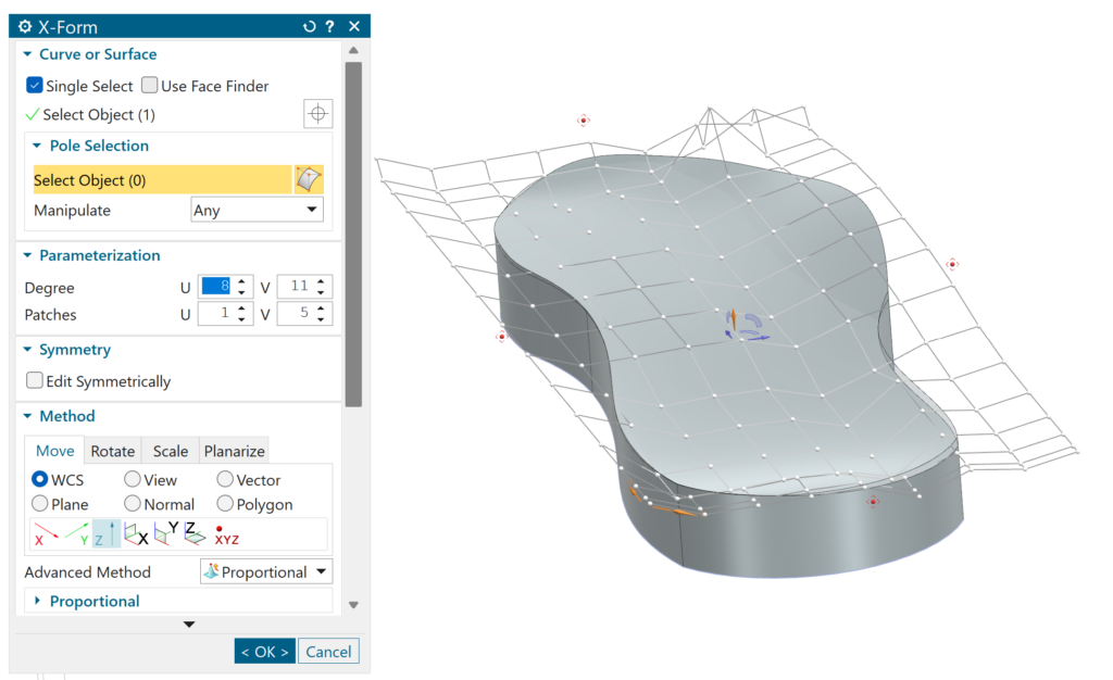
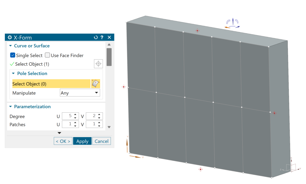
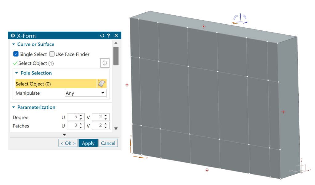
Pole selection and parameterization
The first step in using X-Form is to select the face where you want to make changes. Once you choose the face, you can set up the parameters that will define your new design. When determining these parameters, focus on two main components: Degrees and Patches.
Adjusting the degree changes the number of poles available for editing. The number of patches directly affects how finely you can control the edges of your surface.
You can control both the number of degrees and the number of patches for the U and V directions. These directions are arbitrary coordinate systems assigned when you select the face for design. This flexibility is especially useful when you need to refine and polish your model more along one direction than the other.
After selecting the degrees and patches, you can begin to push and pull your poles and polylines as you start making changes to the surface of your model.
Planarizing your poles and views
Another component for optimizing your experience with X-Form is the ability to planarize your poles. You have various planarize options to suit your needs, but a new feature in the June 2024 release allows you to planarize your polylines so they align with your current view. This feature projects a selected row onto a plane that passes through the two poles with the largest distance in the view, oriented perpendicularly to it.
Other available options include At Plane, At Pole and Best Fit Plane. Each of these alternatives is valuable for different scenarios, so it’s worth exploring them to find what best fits your needs.
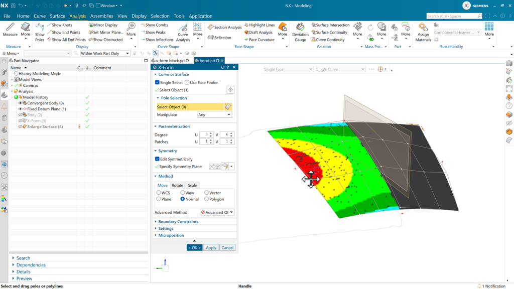
How can Deviation Gauge help?
One powerful tool that can be used in sync with X-Form is the Deviation Gauge tool. This command is used to display deviation data between target objects and one or more reference objects. Results of the analysis can be displayed as visual labels, markers, needles and color maps.
This is a great tool to help during the reverse engineering of complex surfaces. Rather than eyeballing distances until we have a surface that looks similar, we can instead set up a color map scale to indicate when our surface aligns with our target reference body.
Continue your journey with NX
Watch the Molded Part Designer Tips and Tricks video here ▶️
Watch the Performance Predictor Tips and Tricks video here ▶️
Take me to the NX design blog 📚