Avoid overspending on stackup materials in your PCBs – 8 high speed materials to consider
Lets talk dielectrics
PCB material discussions are often focused around stackup material selection. These tend to be framed by questions like: ‘We use material ‘x’ for our designs and really like it. What do you think of it?’ This often veils the real question which is: ‘Do you know a good alternative to it?’
These discussion usually involves a rather expensive ‘name brand’ dielectric material and is seeking alternative stackup materials which accomplish the same task, but are generally more cost effective. As framed, the question is almost always impossible to answer. It would be like telling me you drive a BMW and want a recommendation on an alternative car to purchase; I’m going to need to know a bit more about your current car and what you are looking to do with it.
People tend to be happy to openly talk about manufacturers capabilities, but rarely name drop on the specific PCB material, let alone information on the glass construction or the resin ratio of that material. This may be because they are unsure of these characteristics or values. When you outsource your stackup material decisions to your fabricator you are divorcing yourself from these decisions.

I would love to normalize material discussions amongst our colleagues, having them serve as an opening ice breaker to engage new colleagues and start a dialogue.
Next time you engage with a new colleague, don’t ask about the weather, ask them about their resin system,
Moving beyond your fabricators
The relationships that you form with your fabricators are vital to the build of your board, but ultimately there are a lot of advantages to controlling these decisions yourself. Relying completely on your fabricators for all stackup material decisions can lead to your board being built to conform more to their needs than your own, and the decisions that one fabricator makes regarding your board may not be reflected when production shifts to a different fabricator.
If you are sending designs to your fabricator without an adequate stackup built for it, you are already behind schedule, and if you are looking to turn around your results quickly, then you are generally limited to the materials they have available, or will have to wait for these new materials to be sourced.
To appropriately compare stackup materials, we need to have a level field. Advances in resin systems coupled with changes in glass coverage has led to a large influx of suitable materials for consideration. If your material options are dictated by your fabricators available materials, then the discussion is moot – your choice is dependent upon what they have.
Understanding resin systems
The beginning of this overall discussion really starts with understanding general resin types. FR-4 is still far and away the most common resin type of material used, followed by Polyimide. Where FR-4 is easy to work and inexpensive, Polyimide is harder to manufacture, but more forgiving, with strong thermal properties, allowing high layer count boards to cycle more often.
Exploring Panasonic Megtron 7 alternatives
During stackup material discussions, one of the instances where a material is used by name is Panasonic’s Megtron series. Far and away the most commonly cited material that I have heard people use is Megtron 7. It seems like the ubiquitous high end standard within the industry. It is very commonly carried and it carries a lot of weight with the Panasonic name brand. Someone can say that they use Rogers, but how often do you hear that someone uses Rogers SpeedWave 300P with 1080 construction and 69% resin percentage?
Regardless of our discussion of resin systems, we need to ensure that the comparison at least takes into understanding that the resin system is most likely bundled into a glass construction, essentially a weave type or specific thickness and width, covering various areas over your board. This, coupled with the overall layer thickness will affect the performance of your dielectric, so comparing a 1080 construction at 3.5 mils to a 1078 construction at 3.0 mils won’t serve much of a purpose for direct comparisons.
Lets look at the Megtron series of materials in more depth. I will use Megtron 7 as a baseline, spec-ing the low-Dk “GN” version that is used during Chinese production.
Electrical considerations for your stackup material
If we are looking at high speed designs we are going to be initially interested in the electrical parameters that define the material itself, including both the DF and Dk values to determine the dissipation factor and the dielectric constant of the stackup material and match these with our overall loss budget.
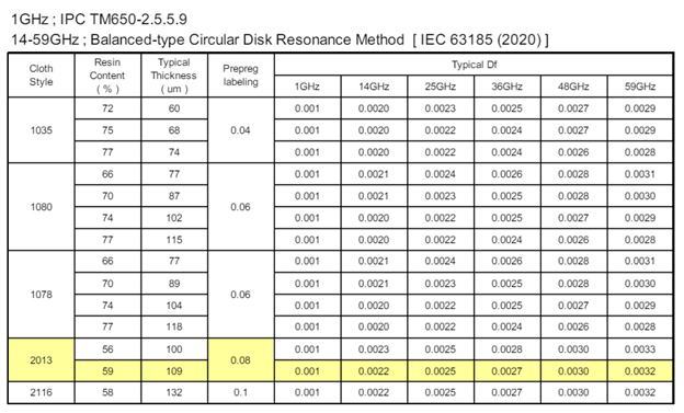
If I choose a construction with a 59% resin content like this 2013 style prepreg and look at the Df values for our stackup material in isolation shows a value of 0.0022 at 14 GHz. This brings it into the ‘ultra-low loss’ category of materials that run from a Df value around 0.005 – 0.0025. There are a dozen or so other ultra-low loss materials available from several other manufacturers with remarkably similar, or better Df values at 14 GHz.
| Manufacturer | Material Name | Df |
| Rogers | SpeedWave 300P | 0.0020 |
| Nanya | NPG-199K | 0.0020 |
| TUC | TU-883A Sp (ThunderClad 2A Sp) | 0.0020 |
| TUC | TU-885 Sp (ThunderClad 400G) | 0.0020 |
| Isola | Tachyon-100G | 0.0020 |
| Isola | I-Tera MT40 | 0.0020 |
| EMC | EM-892K | 0.0019 |
| AGC Nelco | Meteorwave 4000 | 0.0018 |
| AGC Nelco | M-Ply | 0.0017 |
The absolute Df value only tells half of the story here. The second half is looking at the dielectric constant (Dk). These two are directly related to the ratio of resin to glass. At 59%, our cloth selection contained a low resin content material. Within any material the glass is used as a medium for the resin and isn’t a particularly friendly electrical component. Better Dk values, like Df values are lower and lower Dk values allows for thinner materials and narrower traces.
When we do a similar comparison with the Dk values of our Megtron 7 GN material, despite it being targeted specifically as a ‘low Dk’ material, we see remarkably different results from what we saw with our Df comparison.
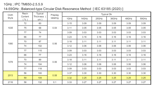
First of all, we see a measured Dk value of 3.25. This number isn’t all that impressive in isolation. We can get literally hundreds of materials from virtually all of the major manufacturers that can reasonably match this value at 14 GHz. This list includes all of the Megtron line, the vast majority of the Thunderclad line from TUC, much of EMC’s 800 series, Isola’s FR408 and IS410, Meteorwave 2000-4000 series from AGC Nelco, and Rogers Speedwave 300. There are not only too many to name here, but there are also too many to reasonably even list in a chart.
If we are looking at comparisons for this specific stackup material with this specific set of characteristics for these two values, presumably if we just combine these two lists and find those materials which overlap on a virtual 1:1 basis we would get the answer. If we are doing this methodology, then M-Ply, ThunderClad 2A and ThunderClad 400G represent reasonable substitutions for Megtron 7 from a purely electrical point of view.
Beyond just electrical consideration
If your PCB’s electrical performance is the only consideration when selecting a material, and you are starting with a high-end option like Megtron 7, then you will have access to a large variety of viable material alternatives at significantly reduced costs. This is because these high-end materials have other attributes which both make them desirable, and costly. There is no case whatsoever where an increase in material performance doesn’t result in an increased cost.
Being able to get your materials performance to match your boards requirements as closely as possible is the key to overall material cost reduction. As your design becomes more complicated, your overall material cost starts to creep upward.
If your design doesn’t have a lot of layers, then you can find saving by relaxing the glass transition temperature (Tg) requirements. If it isn’t going into a harsh environment or a strictly monitored industry, perhaps you can find savings by reducing the peel strength of your material. If you don’t have to use lead-free solder, you could perhaps relax your decomposition temperature (Td) requirement to save money.
Finding stackup materials that match on a single characteristic can allow us to tighten our constraints and save money, but if we are looking for a true replacement across the board, we will have to loosen multiple matching criteria.
Thermal characteristics
Outside of the two dielectric material attributes; Dk and Df, you should generally be looking to also consider thermal variables like Tg, Td, xy-axis CTE, and z-axis CTE. Knowing where you can be flexible on these values relies on the end use of the board, the PCB thickness, and your understanding of how the board will be constructed. Keeping the number of lamination cycles down by closely planning your board’s construction prior to design, or by making use of a hybrid board build-up will allow you and your fabricators to devise a plan and find materials suitably robust for your needs without being over engineered for your design.
To return to our stackup material replacement options outlined above, AGC’s M-Ply has wonderful Dk and Df characteristics but tends to have a much greater Coefficient of Thermal Expansion (CTE) along the Z-axis. The ThunderClad lines also have similar thermal properties, with Tg values 10-20% higher than Megtron 7. Either of these issues could potentially lead to barrel cracking issues along vias that would likely not be present with Megtron 7.
Comparing like results within your stackup materials
While you are examining glass transition temperature (Tg) values when making stackup material determinations, you need to ensure that the manufacturers are using identical test methods to determine the values they provide. In this instance Panasonic has measured Megtron 7 using both DSC and DMA methods (figure 3) to get this measurement. There are a few methods available for measuring this value. In this instance it appears that all the manufacturers mentioned here; Isola, Rogers, EMC, TAC are using DMA to perform this measurement. Even though you are looking at the performance of the same property, there is a lot of variation within this property depending upon the measurement type used.
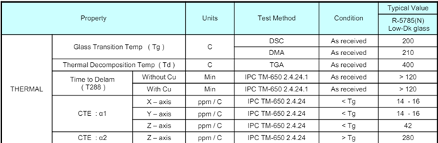
https://api.pim.na.industrial.panasonic.com/file_stream/main/fileversion/251077
This process can be done by comparing multiple material datasheets together and starting with an understanding of the stackup that you intend to create and the manufacturing process that is required to build it.
Rapid material comparisons
Far and away the best way to perform material comparisons like this are by using large material databases. When you create one you can manually compare stackup materials by referencing the material datasheets available on the manufacturer’s websites. I know many organizations make use of spreadsheets of data on material that they make use of during their stackup construction. This can be a great way to compare materials but is also time consuming to keep up-to-date and can lead to situations where companies rely on the same stackup design for years because their entire stackup workflow is scattered among several ad-hoc solutions.
Z-planner Enterprise comes with a very comprehensive materials library designed specifically for stackup design. It is especially handy when it comes to material comparison, as it contains a pre-generated library of hundreds of materials in dozens of configurations with detailed information on all of the physical characteristics available for the stackup material and couples it within a complete stackup planning tool\. This allows you to quickly and easily generate stackups using actual material properties, swap through dozens of stackup material options and iterate designs off of them quickly.
Z-planner Enterprise has a stackup material library featuring hundreds of stackup materials in dozens of configurations, allowing you to easily compare materials by setting your overall material constraints. By loosening some parameters, while tightening others, you can get a good sense of where you can relax your stackup material requirements to strengthen your overall design, while still making true 1-to-1 comparisons. These stackups can be generated in minutes, with output models being instantly testable.
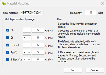
To do a complete comparison on Megtron 7 across all of the available materials for this specific build, we should be looking to match our parameters with a 5-10% specification range. Once we have done this, we get to compare the 7 stackup materials that result.
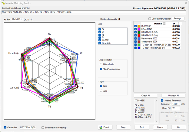
Likely any of these stackup materials will be a good fit to swap out for Megtron 7. From here you would work on pricing and availability with your fabricator to determine the best fit. If your stackup design is performed early in your overall design process there should be plenty of time to procurer specific materials for production.
Stackup Material qualification during post-layout analysis
One of the most interesting times to have this material discussion is during the post-layout analysis phase. Once your design is complete you can push through multiple stackups for rapid verification. In this example, Figure 6, we have performed analysis via Siemens’ HyperLynx on a PCIe 5 board with 336 serial channels using two of TUC’s ThunderClad materials, their baseline TU-885 and the low-cost TU-883C.
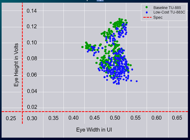
By being able to swap stackup materials within your design and then push them into post-layout analysis is a powerful tool for iterating potential builds. By pushing detailed material characteristics from the dielectric you are simulating what you are going to build, and not what you wish you could build. This specific example is from a 3D solver running overnight on a single rack. You can get similar comparisons in an hour or two if you run a 2D solver on your laptop.
I would encourage you all to continue this discussion within our communities. I think it is great to see this time of communication and ownership of design and I really hope that the next time you meet with a colleague you ask them about their materials.
The latest release of Z-planner Enterprise, 2504 has seen a great deal of improvements within the material matching and section dialog, and contains an expanded list of available dielectric stackup materials for use within your next design.
I greatly encourage you to download and iterate different materials through your stackups with our free online trial of Z-planner Enterprise. It grants you full access to the complete z-planner line of dielectric stackup materials and provides you a chance to perform all of this comparison completely free. stackup material