How much driver jitter is coming from your PDN?
You may not have thought about how your power distribution network (PDN) is contributing to jitter on the output drivers in your design. The performance of a PDN is typically evaluated by generating impedance parameters (Z-parameters) with ports at the IC looking into the power net. The impedance is calculated at a range of frequencies and the goal is to keep it below a certain threshold that minimizes the voltage drop caused by a transient current. Impedance parameters are the primary metric used for evaluating a PDN.
But the current provided to the driver must also arrive consistently from edge to edge. A data driver must produce a varying pattern of ones and zeros, so the frequency of the supplied current must also vary. A Z-parameter plot will tell you how much the voltage will drop at each frequency and will tell you the phase shift through the PDN, but it will not easily show you how that translates to jitter on the output driver.
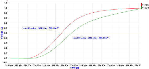
To determine the jitter, we can use a 3D field solver to extract a model of the PDN and use that model in a time-domain simulation. We can then model the way the driver demands current from the PDN and space the demand over a variety of time intervals. If we then measure the time that current was supplied and compare it with the time that the current was demanded, we can calculate the delay as shown in Figure 1 If the delay is the same for every data pattern, then there is no jitter. If the delay varies, we must account for the variation by building in more margin in the design.
By automating the process of generating the driver stimulus and measuring the response, we can easily measure the accumulated jitter and report a maximum value for a given PDN. This becomes a new figure-of-merit for the PDN that considers the PDN’s ability to reproduce driver signals consistently. Less jitter means you can design with tighter margins and produce a higher performance design.
Download my white paper to learn more about the simulation methodology and see how various impedance profiles impact jitter.