Get control of voltage drop with an IR-driven digital implementation flow
IR drop is an ageless problem of chip design. As current flows through wires, the voltage drops, causing transistors to switch more slowly. The Aprisa advanced IR-driven digital implementation flow mitigates the effects to reduce IR-related ECOs so you can tape out faster.
IR drop steals performance and reliability at advanced nodes, especially at higher frequency targets. IR-drop has always been a consideration in IC design, but higher cell densities and routing utilization in today’s circuits make dynamic IR-drop a critical issue. Some of the negative impacts of IR-drop include:
- Severe impact on cell delays for both setup and hold timing
- Performance variation of up to ~200% near sub-threshold operation
- Introduce noise in the power supply nets from the on-chip power/ground grid
- Conventional methods to address IR hotspots, such as adding power pads and having a robust power network, have limitations in terms of resources. Adding decoupling capacitance (DECAP) cells to hotspot regions may not be effective enough at advanced nodes and adding large design margins to address IR-drop issues comes at the cost of performance, power, and area (PPA).
Aprisa goes beyond the conventional methods to support more comprehensive methodologies to better address IR-drop issues at advanced nodes, including:
- IR-driven place & route flow
- Power grid enhancement: strengthening the power grid over hotspot regions
Let’s look at these methods more closely.
IR-driven place and route flow
Place optimization – During place optimization, Aprisa’s Legalizer performs IR-driven placement, which involves dispersing IR hotspots by spreading out the cells to reduce the total peak current. Subsequent optimizations can recover any timing disturbance introduced by the IR-driven placement.
By default, the IR-driven placer identifies hotspots based on a certain IR-drop ratio. For timing critical designs, the maximum IR-drop ratio can be lowered to minimize the impact on timing.
Post-CTS optimization – During post-CTS optimization, Aprisa performs congestion-driven global placement and IR-driven legalization. It addresses peak currents based on timing windows to minimize dynamic IR violators and avoids, by default, large cell displacements of registers and clock cells.
IR-driven incremental legalization – At any stage during the place and route flow, designers can easily run IR-driven incremental legalization. Towards the later stages in the implementation flow, this option can be used to address minor IR violations by using a lower maximum IR-drop ratio that ensures minimal disturbance to the layout.
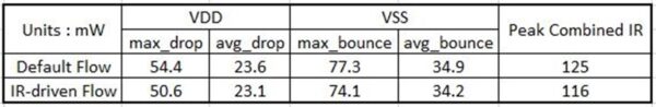
Table 1 shows an example of how Aprisa improved the “Peak Combined IR-drop” by about 7.2% when running the IR-driven flow vs. the regular flow. This is significant for designs that are sensitive to IR-drop.
Power grid enhancement
Typically, IR hotspots are dominated by high switching cells such as clock cells, or high current cells such as big repeaters and registers. The hot spots can span across multiple rows and columns of the power/ground (PG) network. Moving clock cells and registers can improve the IR hotspot, but can severely impact timing/clock QoR. Locally moving the cells with high current demand might help to improve the severity of the specific hotspot but can move the hotspot to a different local region.
These factors mean that IR-driven legalization alone may not be able to address all the hotspots. When that is the case, Aprisa can strengthen the pre-existing power grid. Aprisa’s Power Grid Enhancement utility adds additional stripes in selected areas to enhance the PG connections. In addition to being very effective, Power Grid Enhancement utility is: Automatic, easy to use, DRC aware, and timing aware
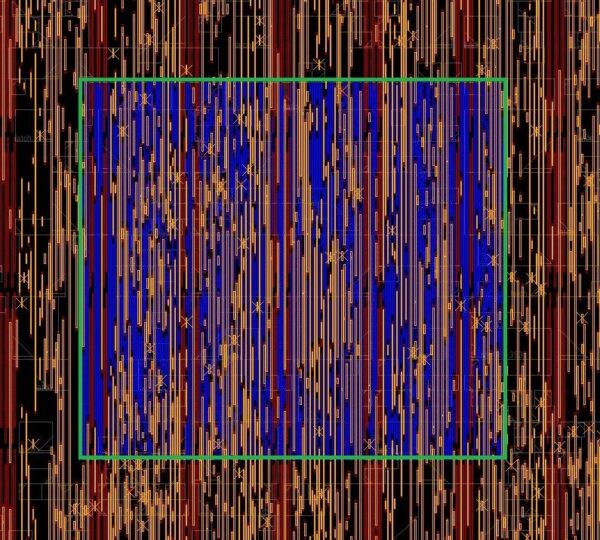
Figure 1 shows an enhanced PG network example. In this case, the database is already routed but Aprisa can add PG shapes from a pre-existing PG network over the hotspot region with just a couple of standalone user commands.
The Power Grid Enhancement utility has several options, the most commonly used options:
- Control the spacing to timing-critical nets while adding additional PG shapes
- Define custom spacing rules for specific nets
While the utility allows lots of customization, users can just use the -timing_driven option, which ensures the timing profile of the critical nets is not degraded.
Debugging IR results
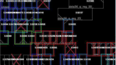
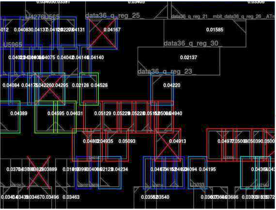
Aprisa offers various ways for debugging IR-drop issues. It has a user-friendly power network map in the GUI browser that can be helpful for analyzing results. You can also use the GUI to see the high peak current values of the cells (Figure 2).
Don’t let IR drop wreak havoc on your designs. Aprisa uses the conventional methods to minimize IR drop and also a full IR-driven flow based on an innovative software architecture and unified data model shared through the entire flow. Aprisa offers fast, accurate design closure and ease of use for today’s advanced node designs.
Learn more by visiting the Aprisa resource library.