DVCon 2024 – Verify Real Number Models

Solving Puzzle
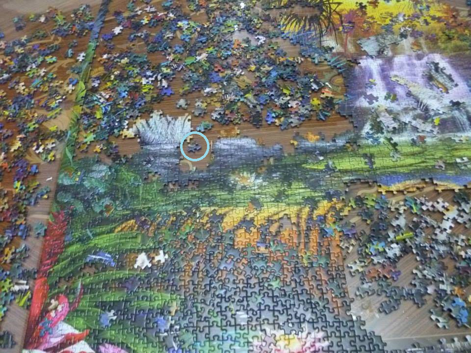
Do you like to solve puzzles? I do, and I think every engineer does.
Since we are solving puzzles every day, there is always a masterpiece that could complete your puzzle.
The masterpiece could be any internal piece of puzzle that could complete your final image. Verifying the complete image of your puzzle by putting internal pieces one after another, could help make you reach the final picture.
UVM
UVM is like a piece of a puzzle where it’s used to complete the whole picture of your design. Digital Verification engineers have been solving their verification puzzles using the UVM from the inputs and outputs of a design. But what about the internal signals and UVM? And what about Analog device “verification”? Analog devices can benefit from advanced verification techniques. This can be done with interfaces and bind. The internal signals can then be forced by random values.
// Interface
import volt_pkg::*; // pkg has a UDN
interface ADC_IF_INT (
  input logic CLK,
  input real vref1, // To access reference voltages
  input real vref2,
  …
  input real vref7,
  output volt D1, // UDN holds resolved voltage To record output of comparator
  output volt D2,
  …);
endinterface

// Binding/force
module top ();
… // Binding DUT to internal interface
bind FLASH_ADC ADC_IF_INT int_if (.CLK(CLK), .vref1(FLASH_ADC.RES_DIV.vref1), .vref2(FLASH_ADC.RES_DIV.vref2),  …
 .D1(FLASH_ADC.COMP.D1),
 .D2(FLASH_ADC.COMP.D2),
  …);
always @(CLK) begin
  force FLASH_ADC.RES_DIV.vref1 = FLASH_ADC.int_if.vref1;
  force FLASH_ADC.RES_DIV.vref2 = FLASH_ADC.int_if.vref2;
  …
end
endmodule

// uvm_sequence_item for the internal signals
class adc_transaction_in extends uvm_sequence_item;
 …
// Randomization of Internal Signals
 rand real vref1;
 constraint c_vref1 { vref1 inside {[(1*VREF)/n_levels - (delta/2) :  (1*VREF)/n_levels + (delta/2)]}; };

 rand real vref2;
 constraint c_vref2 { vref2 inside {[(2*VREF)/n_levels - (delta/2) : (2*VREF)/n_levels + (delta/2)]}; };
 …
endmodule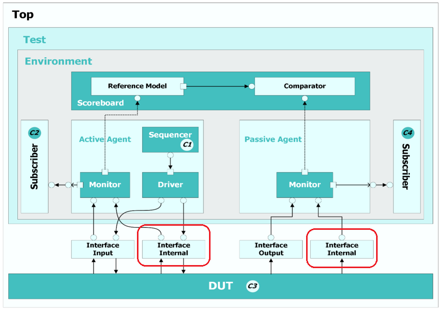
Scoreboard
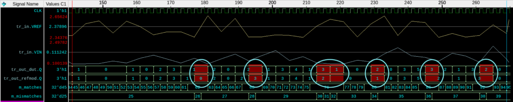
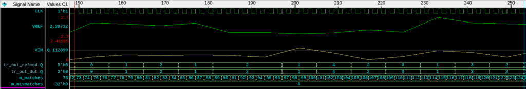
Now we have to check if the device will behave in a correct way after putting the internal pieces of the puzzles together. Which means checking the functionality after driving the internal signals with the randomized values. The scoreboards can check on this, by building a model that defines the behavior of your device – a reference model. The output of the reference model can be compared with the outputs of the DUT. The reference model is the expected model that gives the correct outputs from the DUT.
See you at DVCon 2024
If you are interested in completing your design and solving more puzzles especially the ones that are interested in modeling and verifying the analog devices in the digital environment. Please come and attend DVCon US. 2024.
See you at the paper or at the Siemens booth.