Aircraft Certification: analysis from the conceptual design

The benefits of using aircraft analysis and simulation in the certification process of aerospace structures is extensive. Organizations using simulation and analysis tools effectively and maximizing their capabilities find they can achieve certification faster and with drastically less total cost than those who do not.
The certification of an entire aircraft structure is extremely complex. There are different aspects an applicant for structural approval must consider to prove that the strength of that structure sufficiently meets the design goals of the entire system.
All aspects of the structural certification are subject to the Federal Aviation Regulations which spell out the requirements of the structure depending on the type of aircraft. Engineers must adhere to these requirements by looking at every possible condition and operating environment that the aircraft could possibly operate and demonstrate by analysis or test that each production copy will perform as intended and without any structural failure.
Requirements and Criteria Begin in Preliminary Design
Fundamental analysis begins very early in the stages of conceptual design. The structure necessary to support the entire aircraft depends on the design mission of the aircraft in question. How high and fast will this aircraft need to fly? What is the payload, people or cargo, and how much payload will it need to carry? How far will it need to fly to deliver that payload? These are the fundamental design criteria that affect the type and size of aircraft an airframe manufacturer will need to address as early as possible.
Once the type and size of aircraft is determined the manufacturer typically designs the outer aerodynamic shape of the aircraft; the basic airfoil shape that will meet the mission, the planform area of the wing, the volume and shape of the fuselage, and the airfoils and size of the empennage, the “tail” of the plane.
Loads and Static Strength
The next large scale general step in substantiating the structure takes the aerodynamic general arrangement definition of the new airplane. Conducting a comprehensive analysis evaluates what aerodynamic loads are applied to the aircraft at all the various points of the airspeed or flight envelope.
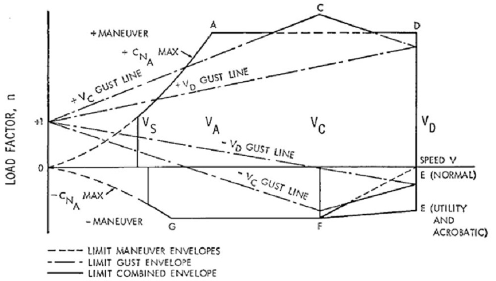
Figure 1 shows an example of a flight envelope for a propeller-driven plane. The Load Factor (n) is calculated based upon the various design airspeeds for the particular aircraft. The various speeds listed are:
- Vs = stall speed
- Va = maneuver speed – this is the highest speed at which the maximum deflection of the controls can be applied
- Vc = cruise speed
- Vd = dive speed
These speeds are input to a Loads Analysis, which evaluates the maximum loads and the associated aircraft condition and configurations.
What engineers must do is analyze and find the biggest, worst case forces that will shear, twist and bend, such as bend up, down, forward, and rearward, ALL the various parts of the structure. They must investigate what the loads are at all the various aircraft weights, centers of gravity, at high and low speeds. At each of these points on the envelope the engineers must determine the loads associated with certain aspects, such as gear up/down, the flaps up/down, and every possible combination of the configurations.
The critical design loads and the critical conditions are the highest load for each and every combination of points on the envelope and each condition. There are literally hundreds of combinations of points and configurations on the flight envelope to evaluate and investigate.
For example, the critical condition for wing spanwise bending — imagine pulling straight up on the tips of the wings and holding fixed where the wing attaches to the fuselage — is at a heavy weight in the cabin when there is little fuel in the wings and the aircraft is at the maximum prescribed gust load. At the point, the wing is lifting up, and the gust is pushing the aircraft down so the wing bending is the highest in this condition.
From there, aircraft analysis of the actual physical structure ensures the static strength is sufficient in every possible operating point the aircraft could see in service. The critical loads are then called the “design limit” loads. In general, the FAA requires static-testing of the structure and that a minimum load of 1.5 times the design limit load (the ultimate load) be applied. While the structure may flex, it can show no failure, not even a crack, or any evidence of permanent deformation; this would indicate the structure entered a critical area in its material property limits. While all of this is happening, there are ongoing detail design changes to the physical structure. Robust and disciplined configuration management is absolutely critical at this stage.
About the authors
Dave Chan is a technical account manager supporting the aerospace, defense and federal business for Siemens PLM Software. His career with Siemens PLM Software started in 1996, and he has driven customer success with the adoption of digitalization and digital engineering solutions for numerous commercial and federal customers. Dave has been in the engineering software business for more than 22 years. He has a bachelor’s degree in industrial engineering from Lehigh University.
John Cunneen is a business development consultant for Siemens PLM Software’s Aerospace, Defense, Federal, and Marine division. He leads efforts to uncover, develop, and respond to industry and government requirements pertaining to all aspects of product and system lifecycle management and provides thought leadership to customers. John has been an avid general aviation pilot since 1987, earned a Bachelor of Science in aerospace engineering from Arizona State University in 1989, and has been a key part of Siemens PLM Software since 1999.


Comments