Aircraft Certification: using analysis and simulation for the airframe structure

In our previous blog, Aircraft Certification: the benefits of using analysis and simulation, we discussed how the fundamental analysis begins at the conceptual stage including analysis of load and static strength and determining the ultimate load.
In this blog, we will continue discussing the complexity of certification for an entire aircraft and the importance of simulation, analysis and testing throughout the entirety of the process.
Fatigue and Aeroelastic Considerations
As important as static strength is to the overall reliability and safety of the aircraft, it is not the only structural consideration. Engineers must also design the airframe structure to meet the physical rigors and long-term effects of repeated flexing of the structure, which pertains to fatigue strength. The structure flexes in flight when under changing aerodynamic loads so it needs to be evaluated for structural stability in these dynamic conditions. These investigations are the Fatigue and Flutter substantiations and involve just as much rigorous analysis and test as the static test program.
Aircraft Fatigue Analysis
If you have ever bent a paper clip back and forth until it breaks, you have performed a fatigue failure on that piece of wire. Bending a paperclip will permanently deform it and actually hardens the metal locally. The paper clip becomes less “plastic” where it has been deformed. Bending it back and forth, over and over, increases this internal hardness until it cracks and breaks. This is a fatigue failure. Most metals flex a little and return to their original shape before they become deformed. In normal operation, wings flexing up and down over time, multiple times is analogous to our paperclip.
If the design of the airplane is right, the wing will be in the linear part of its composite stress/strain curve when applying a repeating bending force up to and including the design and ultimate limits. (Figure 1) The structure will flex and return to its shape but will not permanently deform.
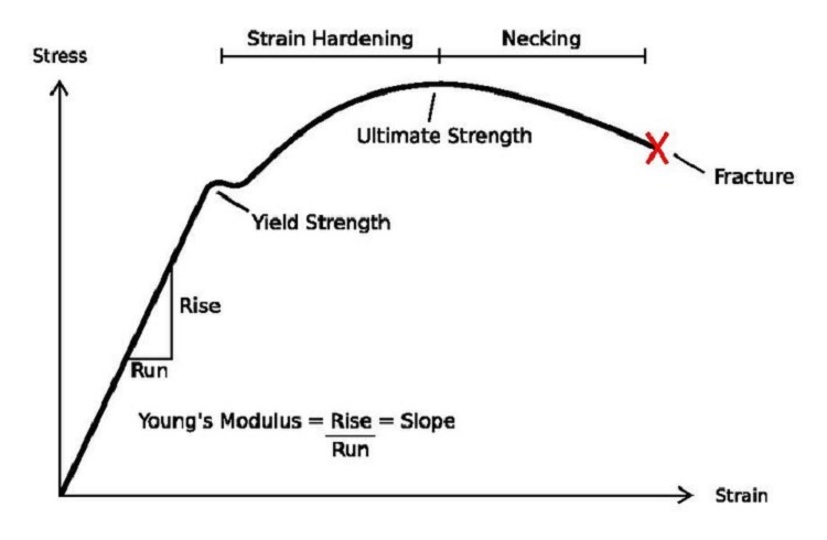
But even within this linear range of the stress/strain curve, sometimes with enough cycles, any material will succumb to fatigue failure. The guidelines engineers use to determine the long-term effects of this repeated flexing are called S/n diagrams (Figure 4).
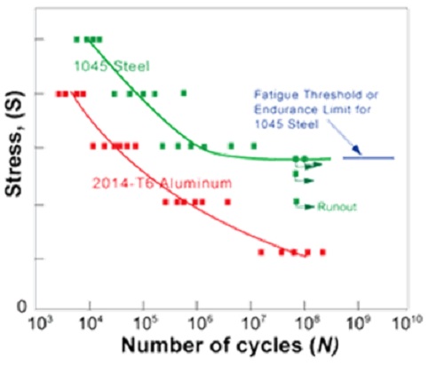
The engineers must ensure the number of cycles the aircraft is expected to see in service, as estimated by empirical data with some level of factor of safety assumed, never gets close to the fatigue failure limit of the various parts of the structure.
Flutter Evaluation
An additional impact of a flexing structure and a structure that is designed to be in motion deals with both the dynamic and aero-elastic effects of that movement and flexing.
Every physical article has some natural harmonic frequency that it tends to vibrate. The simple example is that of a ruler held fixed a one end and allowed to be cantilevered at the other. Picture clamping the first inch or two of the ruler on a table edge and letting the other end extend into free space. If the free end is bent up or down and released from a bent position, the ruler bounces like a diving board. The initial frequency of that vibration is the natural harmonic for that material and shape. Friction naturally dampens the vibration until it comes to rest. If you introduced an external pulse at the same natural harmonic frequency, that ruler would keep vibrating until that pulse was removed.
Upsets in nature in the atmosphere like wind gusts and turbulence is just like introducing an input vibration into the free end of the ruler; the flexing and resulting vibration of the wing is just like the ruler clamped to the end of the table.
The vehicle needs to be evaluated with respect to this movement by introducing varying frequencies of vibrations and ensuring that at no time is there a harmonic mode that could lead to a long term or very short duration flutter, especially one where the amplitude (deflection of the structure) gets bigger and bigger. The result could be catastrophic in the case of a divergent flutter mode where the structure can literally be torn apart from the resulting vibration.
The Role and Importance of Simulation, Analysis and Test
The inherent value of performing the simulation studies is to predict the behavior of the system without investing time, money, and effort into producing iterations of test articles for physical testing.
Needless to say, there will always be a need for physical testing. However, simulation analysis can supply sufficient results reducing the need for a test to satisfy a required means of compliance.
Aerostructure sizing requires computing thousands of structural analyses that feed into aircraft airworthiness certification. A lack of consistency in getting the right data for stress analysis and using the right engineering methods, sharing work and publishing stress reports makes the aircraft certification difficult and long.
Automating and standardizing the process are key challenges for airframe structural analysis. Maintaining visibility and traceability of specific data, models and process/methods from concept to end product is a constant struggle.
The global simulation process means many engineering teams work closely together; from computer-aided design (CAD) definitions to computer-aided engineering (CAE) model and stress analyses. Automating the process speeds up and improves the efficiency of design-simulation iterations.
By using end-to-end processes for aerostructures that take advantage of simulation throughout the product lifecycle, manufacturers have found they can deliver innovative products on time and with predictable performance. From the perspective of the owner-operators, this will also impact how quickly and accurately the necessary analysis work can be completed as part of continuing airworthiness.
These processes have enabled them to reduce model preparation time, shorten design-analysis iterations, evaluate trade-offs across multiple disciplines, streamline development for on-time delivery and improve the quality of designs. Process standardization helps tackle this problem by improving process consistency and limiting the risk of errors that reduce availability and readiness.
The pervasive industry need is a comprehensive collection of simulation plus, advanced methods test, and data management tools that streamlines the global simulation process from facilitating CAD geometry definitions to providing a CAE environment.
A digital certification platform meets that need. Comprised of an integrated system that encompasses the many analyses and reports required for readiness certification in a transparent environment, a digital certification platform maximizes traceability and knowledge capture. It includes:
- Automated integration of loads and geometry to construct assembly finite element stress simulations
- Integrated capabilities which will calculate margin of safety
- Seamless report generation associated with system requirements via the PLM system.
A complete aerostructure simulation solution enables traceable data and results while maintaining consistent global process control. In addition to a detailed finite element model (FEM) approach, end users can size aerostructure components using a library of analytical engineering methods. With the capability of generating stress reports with data and results of the simulation, end users benefit from a consistent and integrated global process, resulting in increased accuracy, time and cost savings, and increased availability over the product life cycle.
Automation and standardization challenges in airframe structure analysis for airworthiness certification can be mitigated by integrating a simulation environment covering the full simulation chain. This would provide a comprehensive digital twin that would encompass the capture and traceability of customer requirements, data, knowledge and processes.
About the authors
Dave Chan is a technical account manager supporting the aerospace, defense and federal business for Siemens PLM Software. His career with Siemens PLM Software started in 1996, and he has driven customer success with the adoption of digitalization and digital engineering solutions for numerous commercial and federal customers. Dave has been in the engineering software business for more than 22 years. He has a bachelor’s degree in industrial engineering from Lehigh University.
John Cunneen is a business development consultant for Siemens PLM Software’s Aerospace, Defense, Federal, and Marine division. He leads efforts to uncover, develop, and respond to industry and government requirements pertaining to all aspects of product and system lifecycle management and provides thought leadership to customers. John has been an avid general aviation pilot since 1987, earned a Bachelor of Science in aerospace engineering from Arizona State University in 1989, and has been a key part of Siemens PLM Software since 1999.TOPICS