Hierarchical DFT: How to Do More, More Quickly, with Fewer Resources
By Rick Fisette, Mentor Graphics
Is DFT a barrier to tapeout? Time to consider going hierarchical.

Today’s large System-on-Chip (SoC) designs present many challenges to all design disciplines. Tool runtime and the amount of memory required to load designs continue to grow and stretch available resources and design schedules. For Design for Test (DFT), much of the design and pattern generation activity have traditionally taken place late in the design cycle which puts it in the critical path to tapeout. As tool runtimes increase and different design disciplines vie for the same compute resources, DFT poses an even greater barrier to a timely tapeout.
Hierarchical DFT Overview
A hierarchical DFT methodology is specifically targeted for the challenges of large SoCs. The basic concept is a “divide and conquer” approach. Each core corresponding to a layout block is isolated by wrapper chains. When implemented properly these wrapper chains add negligible gate area but the isolation they provide make it possible to test each core separately. In Internal mode, a core’s wrapper chains are configured to test the logic within the boundary of the wrapper chains. In this mode, only the netlist for the core needs to be loaded in the ATPG tool for pattern generation, as shown in Figure 1.
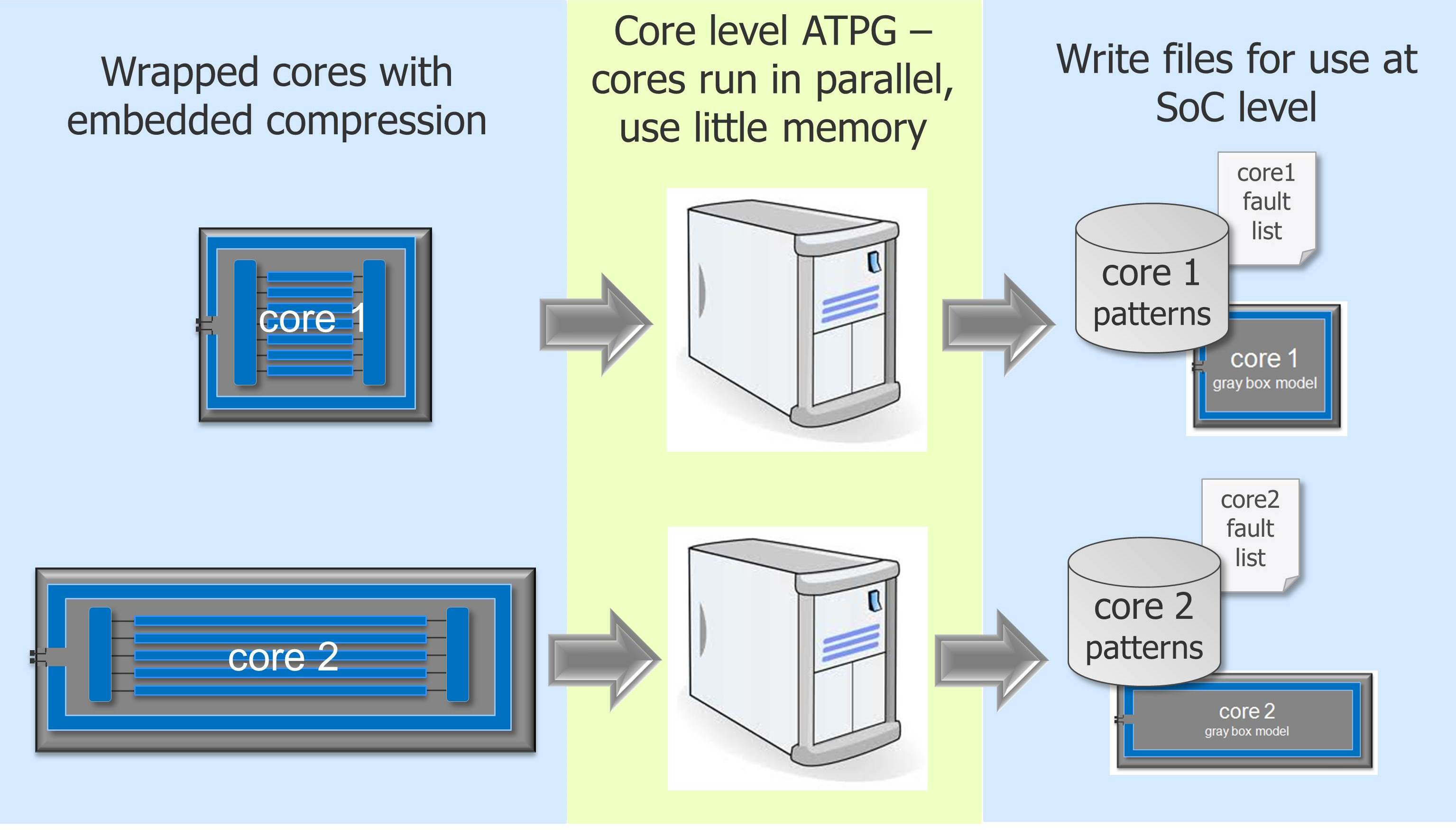
Figure 1. Core-level test pattern generation.
In addition to generating patterns at the core level, the wrapper chains are also verified through simulation with fully back-annotated timing. One last core-level step is to generate a graybox model of the core that only contains the wrapper chains and logic outside the wrappers, as shown in Figure 2. This interface model is used to represent the core for subsequent SoC-level steps.
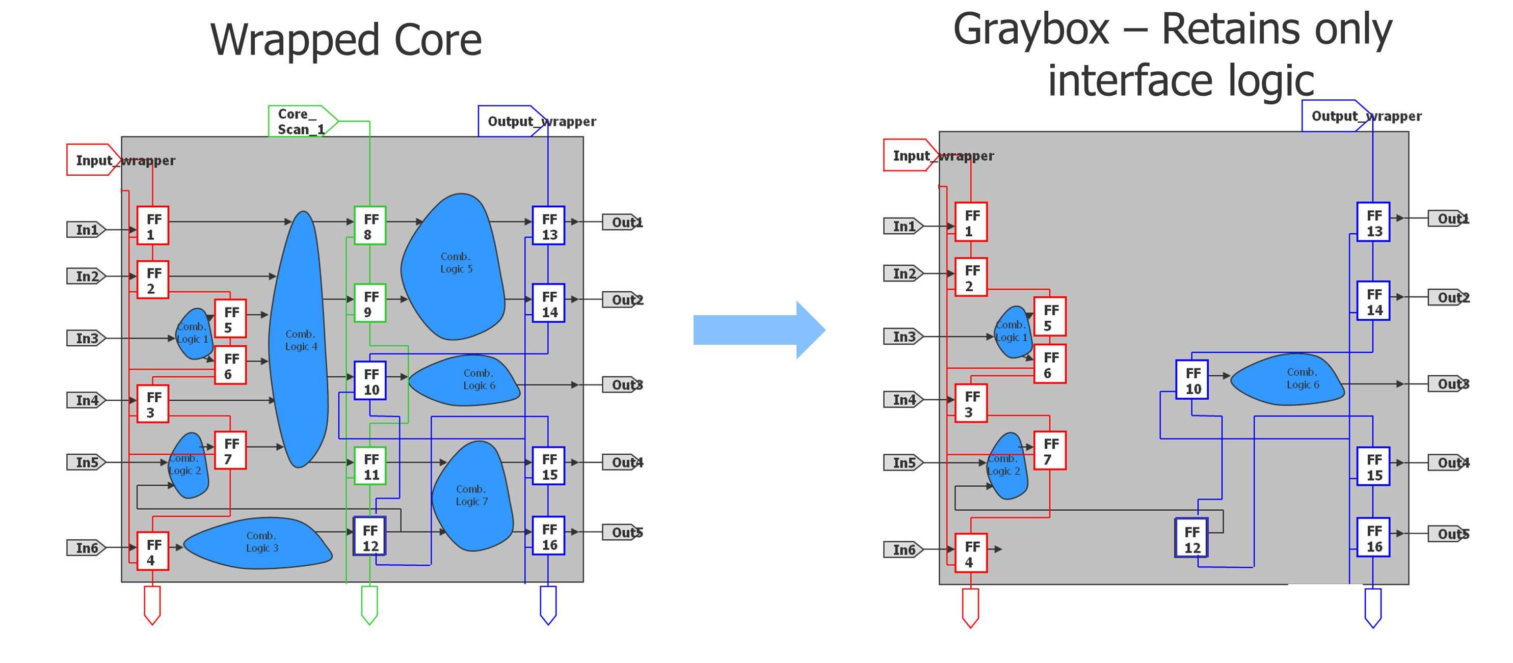
Figure 2. Greybox generation.
Internal mode patterns are then simply retargeted to the SoC-level pins. Even with very few chip-level pins available, cores can share access to these pins and be tested in separate phases. The retargeting done by Mentor Graphics test tool, Tessent TestKompress, will automatically account for pipeline stages and inversions in the scan path and merge patterns together for both identical and non-identical cores, as shown in Figure 3.
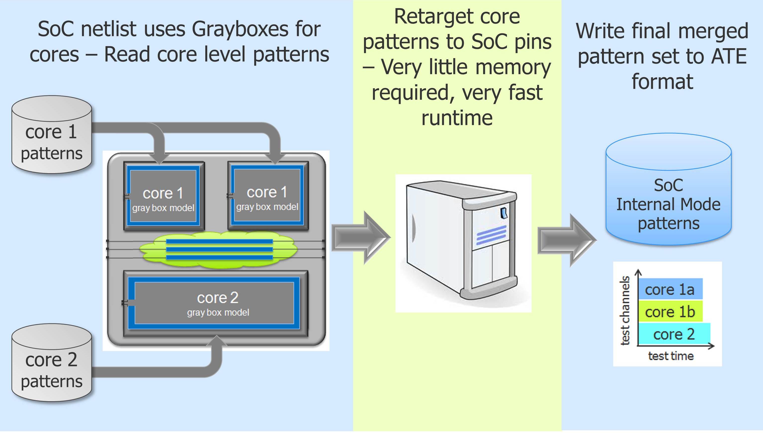
Figure 3. Retargeting core patterns to the SoC level.
The remaining SoC-level logic and interconnect are targeted in External test mode. In this mode, the wrapper chains of the cores are reconfigured to launch from output wrappers and capture on the input wrappers. This relatively small pattern set only requires that the SoC-level netlist and grayboxes be loaded in the ATPG tool. This keeps memory footprint low and runtime short.
The test coverage results of External mode are then automatically merged with the coverage of the Internal mode pattern sets so that a single comprehensive SoC test coverage is reported, as shown in Figure 4.
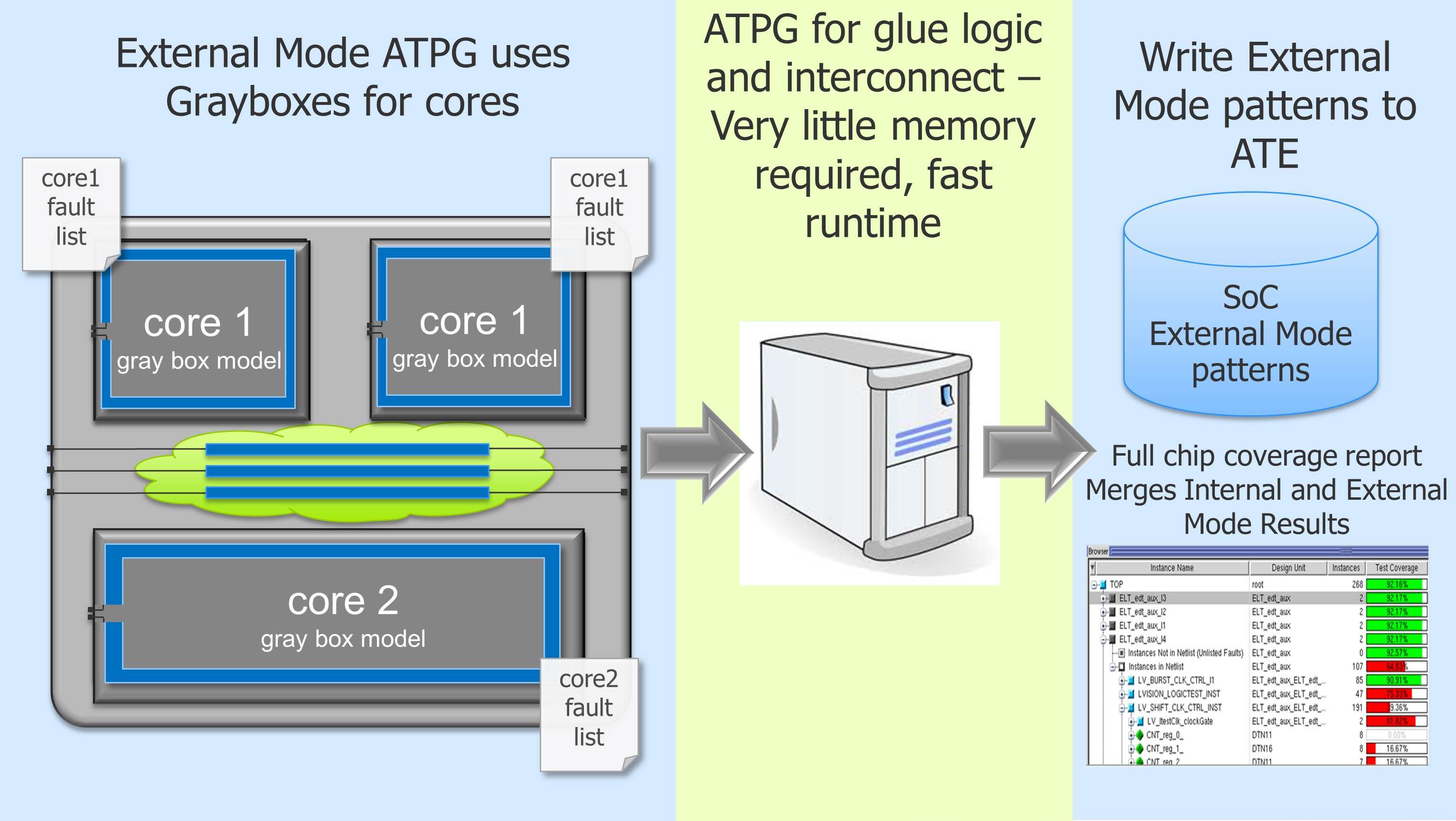
Figure 4. External mode pattern generation.
Pattern Retargeting Benefits
Hierarchical DFT techniques have been in use for some time but new automated capabilities like pattern retargeting significantly enhance the advantages of the hierarchical test. Core-level generated patterns benefit from better efficiencies in clock control and scan channel allocation, which typically result in a 2X reduction in pattern count. The most obvious benefit is that ATPG runtime is reduced by as much as 10X. Even more significant, though, than the days of runtime being eliminated is when it is being eliminated. Pattern retargeting makes it possible to generate and verify scan patterns very early in the schedule as each core is completed. Instead of waiting until very late in the schedule for a final SoC netlist before generating and verifying scan patterns, these time-consuming tasks are shortened, performed across all cores in parallel and completed much earlier in the schedule. Hierarchical DFT with retargeting removes DFT from the critical path to tapeout.
Another DFT task that holds up tapeout is regenerating SoC-level patterns when logic changes are made to the final design due to bugs found late in the verification process. Rather than regenerate patterns from the SoC level, retargeting enables one to quickly regenerate patterns for just the affected core.
Another benefit of pattern retargeting is the up to 10X reduction in memory required for running ATPG. Since CPUs with much less memory are typically more widely available it is now possible to take greater advantage of distributed processing capabilities, further reducing runtimes. Because ATPG no longer needs the largest CPUs, those machines become more available for other design disciplines such as physical design and verification to complete their tasks.
Conclusion
Hierarchical DFT, specifically with pattern retargeting, can provide as much as 2X reduction in pattern count as well as 10X reduction in memory and runtime required for generating and verifying scan patterns. More importantly, DFT tasks are completed at the core level early in the schedule. This removes DFT from the critical path to tapeout and improves time to market.

Liked this article? Then try this –
White Paper: Hierarchical DFT for SoC Designs
This article was originally published on www.chipdesignmag.com