New test points slash ATPG test pattern count
By Ron Press, Mentor Graphics
Want to see a big reduction in pattern count compared to the best ATPG compression?

Scan testing has been the foundation of digital-device production test for many years. Several innovations have been developed to keep up with the growth in pattern-set sizes brought about by large designs and the need to test for new types of defects. Previously, the big reductions in pattern application time and data were based on improving the interface between the scan chains of the functional design and tester channels, such as with embedded compression. Now, there is a new approach that greatly improves the ability to efficiently test multiple faults per pattern. This approach applies a new type of test point identification to EDT (embedded deterministic test). The results we’ve seen with the EDT Test Point approach averages 2x to 4x reduction in test-pattern count beyond what already exists with embedded compression.
A scan pattern is the set of test cycles needed to load all the scan chains, then capture the results, and unload them. The load of one pattern overlaps with the unload of the previous pattern, so the number of test cycles is equal to the sum of scan load and capture cycles. To control test costs, pattern compaction techniques have long been used to reduce the number of scan patterns. Static compaction adjusts the order of patterns applied to identify redundant patterns while dynamic compaction improves how many faults can be targeted within individual patterns. Historically, these compaction approaches were purely algorithmic and didn’t require any changes to the design. As the industry started to adopt transition patterns, there was suddenly a demand to cut test time and data volume in half. This is when embedded compression technology was introduced, providing over an order of magnitude reduction in test time and data. With embedded compression, such as EDT, logic is added to the scan chain interface in the design itself.
EDT doesn’t directly reduce the number of test patterns. It significantly reduces the number of cycles necessary for a scan pattern by using more scan chains but the same or fewer tester scan channels. That lets the tester load in a way that the time (and data) applied an individual pattern can be hundreds of times less. For example, say a design has a single chain 5000 scan cells long and needs over 5000 cycles per pattern. With EDT, the signal tester channel could be used, but with 100 scan chains of length 50 and take only 50+ cycles.
The compression technology takes the few serial scan channels from the tester and expands that data to the many internal scan chains on the input side and compacts them on the output side. Our EDT technology requires on average less than 1% additional logic be added to the design, which is located only in the scan path so it doesn’t impact the functional logic.
Today, with the growing usage of cell-aware patterns and sometimes other patterns to improve the test quality and manage the continued growth in design sizes, we see even bigger demands on test time and data. As a result, many are starting to utilize the new EDT Test Points technology. This approach to test point identification and insertion focuses on finding locations in the design that improve the ability to target one or multiple faults. EDT Test Points produce compression-optimized test points that work with EDT technology and any pattern types.
While test points have been available with logic BIST for two decades to improve control and observation of logic, these traditional test points do little to reduce test time or improve test coverage for scan test. A 15% to 30% reduction in test time is not enough improvement to have led many companies to implement test points just for scan testing. The new EDT test points, however, work very differently and have a different goal—to directly reduce ATPG pattern volume by improving the ability of the ATPG engine to efficiently generate patterns.
One way EDT Test Points improves results occurs in Figure 1. In this example, if half the faults are in logic cone A and half are in B, then the pattern size would be the sum of patterns needed to detect faults in cone A plus patterns for cone B because only one cone can propagate to an observe point. Note that the control for any fault in cone A or B might be easy to set using the control input so this issue wouldn’t be identified by traditional test points.
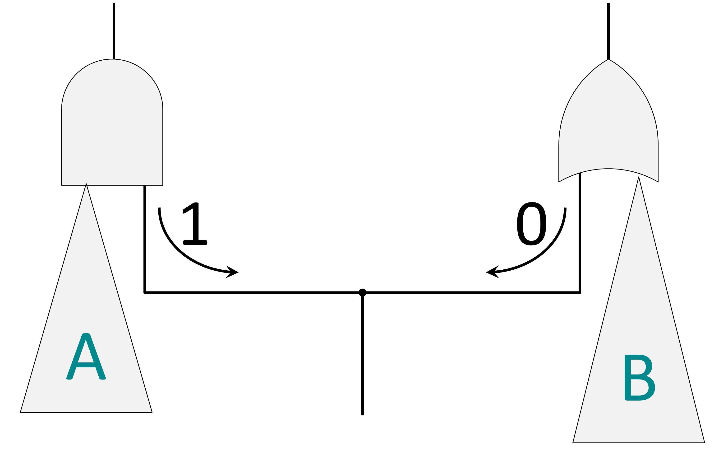
Figure 1. In this example, pattern size is the sum of patterns needed to detect faults in cone A and for cone B.
If we add the simple test point shown in Figure 2, then we can reduce the pattern count for this logic by up to 2x with only that one test point. This is a simple fabricated example, but it is easy to see how such a test point can have a big impact. By adding 1% to 2% test points, we have seen 2x-4x reduction in pattern count. Table 1 illustrates the trade-off between the number of test points and the reduction in pattern count for one particular design. EDT Test Points are a new type of test point technology that gives big payoffs in pattern count reduction over what you can get with the best ATPG compression.
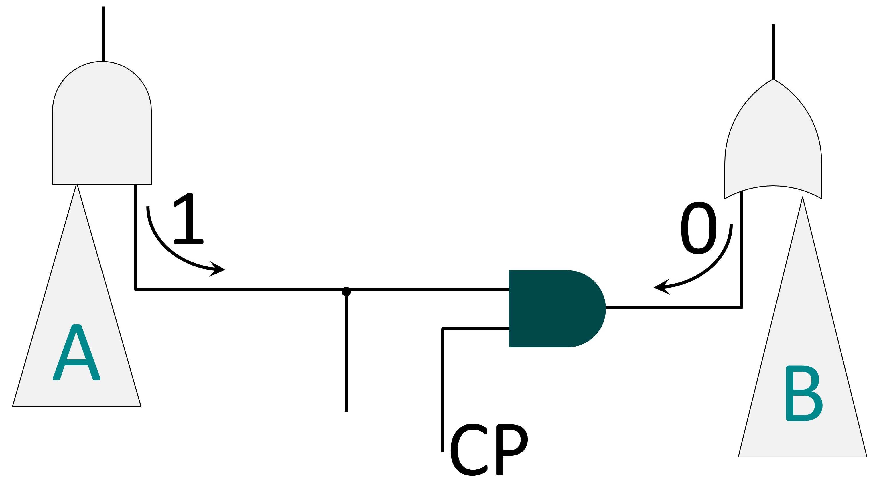
Figure 2. Adding a test point (CP) reduces pattern count by providing more access to the circuit under test.
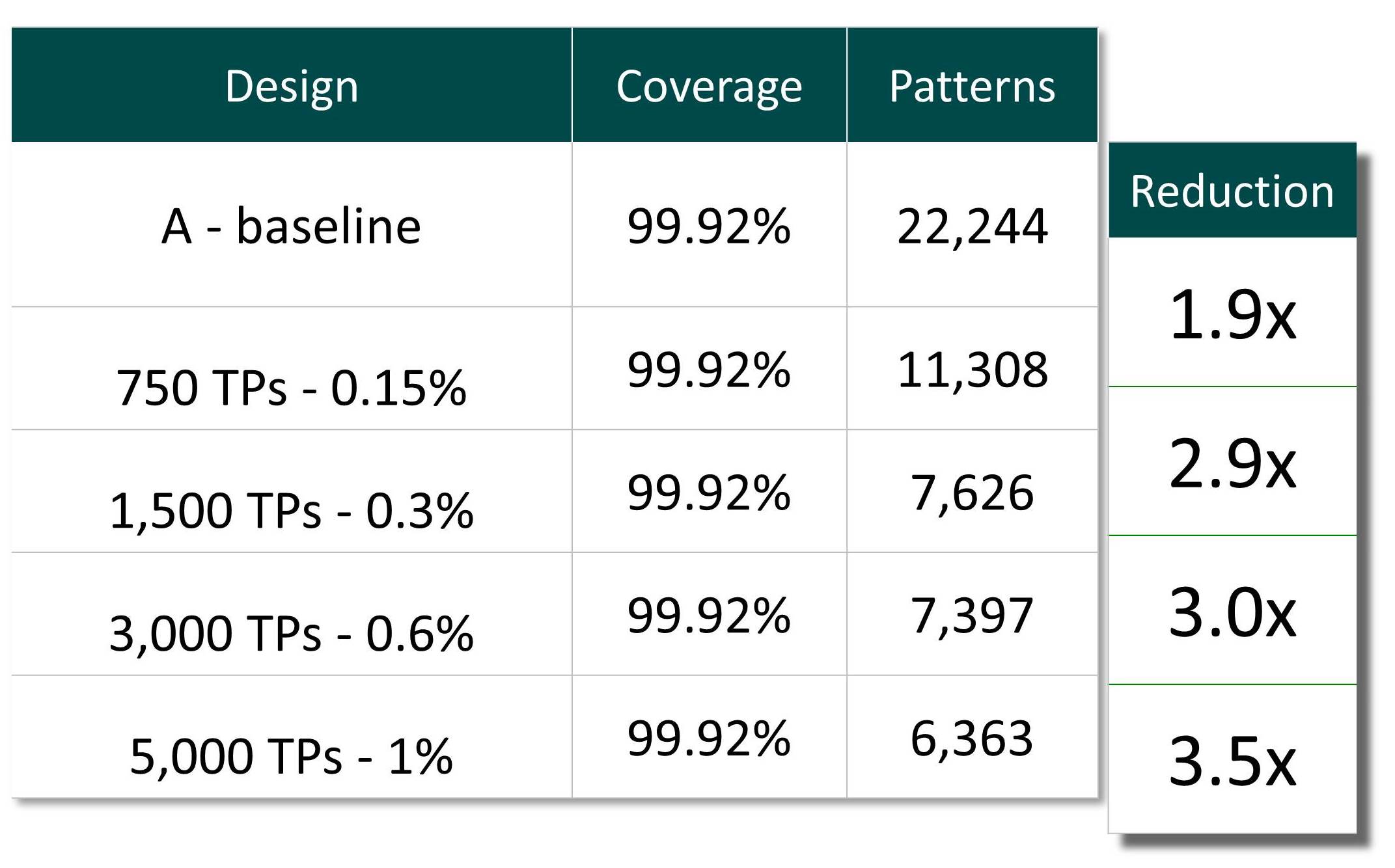
Table 1. Test pattern count vs. number of test points.

Liked this article? Then try this –
White Paper: EDT Test Points
This article was originally published on www.edn.com