Tecnomatix Plant Simulation 15 – What’s New?
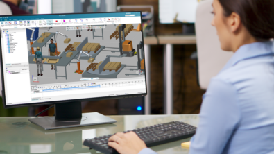
Tecnomatix® Plant Simulation software is designed to model, simulate, explore and optimize logistics systems and their processes. These models enable analysis of material flow, resource utilization and logistics for all levels of manufacturing planning from global production facilities to local plants and specific lines, well in advance of production execution.
In this latest release of Tecnomatix Plant Simulation we have focused on the area of material routing on conveyor systems and machines and added additional strategies and capabilities for operators carrying parts, making it much easier to set up and maintain simulation models for manual production processes. Additionally, material transport through transporters and vehicles driving directly on the shop floor opens new ways of modeling flexible transportation and logistics systems based on automated guided vehicles (AGV). Completely new functionality is provided with the introduction of cost-related attributes and evaluations. The predefined and extendable cost report covers investment cost as well as material and production cost per piece. You will also find enhancements to existing functionality, like the new Breakpoint Manager, offering a new level of help during debug sessions for your simulation models.
Of course, with any new software version there are many exciting new features to talk about and Tecnomatix Plant Simulation 15 is no exception. We are already working hard on the follow-on releases to Tecnomatix Plant Simulation 15. Stay tuned…
We think you’ll be impressed by what Tecnomatix Plant Simulation continues to do for you! Please let us know what you think in the comments section below.
—–
(Don’t have Tecnomatix Plant Simulation? Try it for free here.)
—–
Here are the main highlights from the release.
Free moving Transporter and AGV
In previous versions of Plant Simulation, the transporter could only drive on a track system. Changing the machine layout on a shop floor leads to necessary changes to the track system, otherwise, the vehicle is not be able to reach the relocated machines. The enhanced transporter object in Plant Simulation 15 can now drive directly on the shop floor. In this way, you get rid of managing and adapting the track system for each layout change. Nevertheless, you need to control the transporter movement and driving path in your simulation. For this purpose, we introduce new marker objects that you can place in the layout. Vehicles can use a marker as a driving target or a list of markers as a driving route. Once you place a marker next to a machine and you move the marker and machine to a new location on the shop floor, you are done. The transporter will automatically find its way to the new location without any additional changes in your simulation model. This simple mechanism helps you in setting up simulation models for flexible AGV systems easily, just by using the new out-of-the-box features. Nevertheless, this first version of transporters moving on the floor does not yet cover all aspects of current AGV systems. We will provide additional functionality, like detection of and interaction with vehicles in the neighborhood, with minor release version 15.1, and so on.

Return to top. ^
Free moving AGV
In the picture below, you see two different variants of the marker object. The standard marker, displayed with orange circles, does not define the orientation of a vehicle at this point. According to the vehicle default curve radius, it may happen that a vehicle just drives along a marker on its way, all the while using smoothly curved driving paths. Every marker can be converted to a rotation marker, displayed as an orange double arrow. The internal path calculation for the vehicle assures for such a rotation marker that the vehicle drives with the exact orientation over this marker. With this feature you can, for instance, assure that vehicles always drive parallel to a station. This is necessary as in almost all cases a material handling system next to the target machine requires an exact alignment of the transporter position.

Return to top. ^
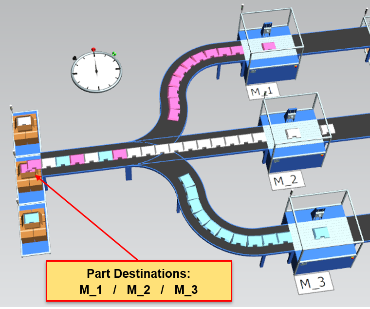
Automatic part routing on lines and machines
With Plant Simulation 15, you can activate a shortest path calculation and automatic part routing for parts on a network of conveyors and machines. Additional material flow objects like buffers or assembly stations are supported in the routing network as well. You just need to activate the automatic part routing and assign a destination or list of destinations for a part. Then, the simulation system will start the Dijkstra shortest path calculation and routes the part according to the calculated path. For information on the current part routing you can hover over a part with the mouse and a pop-up tooltip shows the complete path and the current part location on the route.
Return to top. ^
Part exit strategies and operators carrying parts
Operators have been able to carry parts between machines on the shop floor already for some time in Plant Simulation. We have now added the capability of using the standard part exit strategies defined in a machine or station dialog. This makes out-of-the-box strategies like percentage rule or minimum processing time available for part carrying operations. You can use those strategies in a fast and easy way, without programming the logic in SimTalk.

Return to top. ^
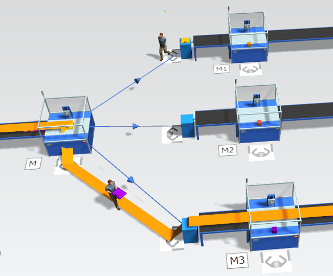
Part routing and operators carrying parts
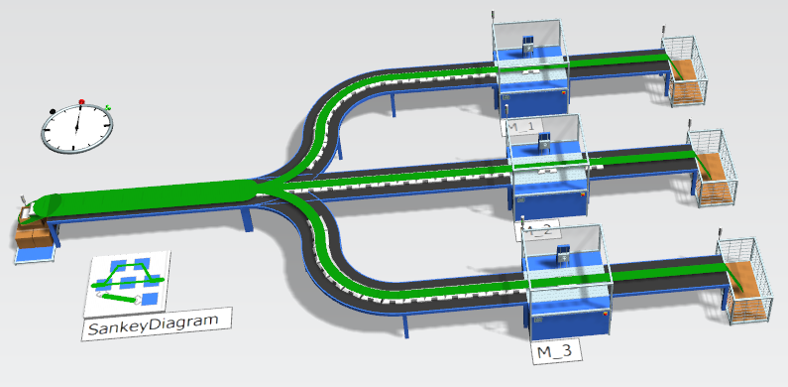
A powerful combination is also now available between the automatic part routing and the concept of carrying parts by an operator. Once a part has a target destination or a destination list assigned, the operator will pick up the part at the exit of a machine and walk with the part to the next destination object, which can be a machine, a station, a buffer, and so on. In the example shown here, the operator transports the part with a destination of station M3 from the station M to the dropping place in front of the conveyor leading to station M3. All of this is done automatically with built-in functionality.
Return to top. ^
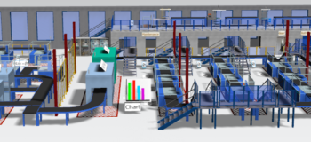
New Sankey diagramming tool
The new Sankey diagramming tool provides very fast visual feedback on any material flow, including worker or transporter movements in a simulation model. The enhanced Sankey implementation is much faster than in previous versions and is now more tightly integrated within Plant Simulation. You can insert several Sankey diagrams in a model with each one observing different object classes like operators, transporters and part types. The Sankey diagram helps in analyzing and validating simulation models. It also helps when explaining a simulation model to your customers or colleagues.
Return to top. ^
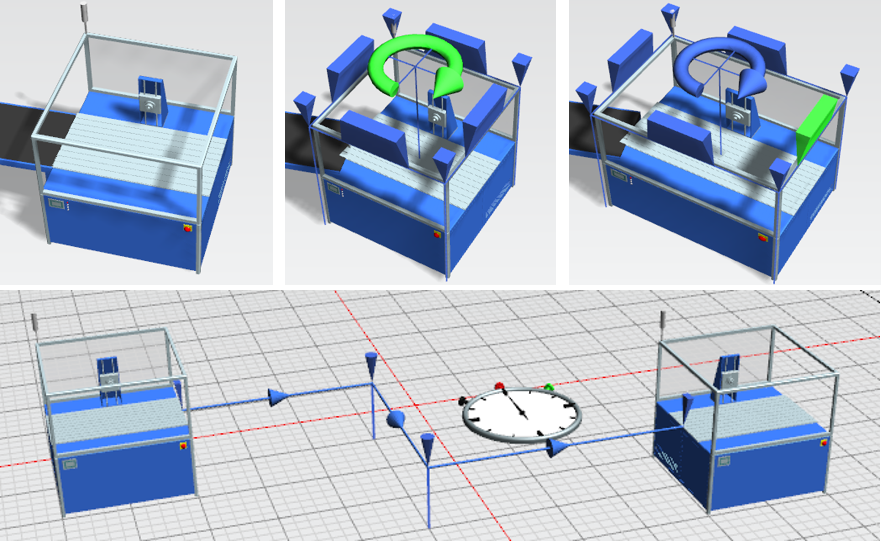
New pose editor for kinematic definition
Modeling material flow simulations in 3D is becoming more and more a standard and the requirements for advanced object and machine animations are growing. A typical example for such an advanced animation might be the opening of a safety window in front of a machining center when inserting a part into the CNC machine. The already existing animation functions in Plant Simulation 3D have now been brought up to a new level. You can define typical joint settings interactively through dedicated tabs on the object’s 3D properties dialogs. With the new pose tab and editor, you can define named positions for several joints, such as “working position” or “feeding position”. You can activate a pose from a SimTalk method. Plant Simulation automatically executes all necessary joint animations to reach the target pose.
Return to top. ^
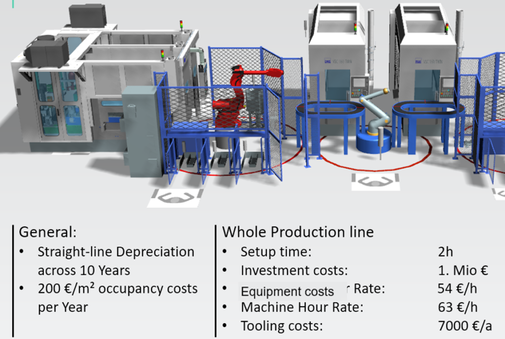
Simulation based costing
A new capability in Plant Simulation is the direct support of production related cost evaluation. Costing could be addressed in previous versions as well, but you had to define all cost attributes and evaluations on your own. Now, we provide standard cost attributes for material cost on parts and operating costs for machines and stations. Plant Simulation also offers investment costs and deprecation periods for machines. At the end of a simulation study a predefined Cost Analyzer collects a summary on investment costs and calculates the production costs per piece. The cost report can be displayed as part of the available HTML report.
Return to top. ^
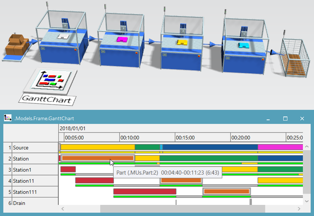
Gantt chart migration to Plant Simulation core
The new implementation of the Plant Simulation Gantt Chart add-on brings a big performance improvement to our customers. The Gantt Chart is now directly implemented as core functionality in Plant Simulation, improving the display performance by more than a factor of 10. The state-of-the-art user interface and tooltip information on the chart itself give detailed information on machine usages on observed parts. You will be surprised by how fluid the charting tool is, even for large datasets. Give it a try with some machines that you drag to the Gantt object for observation!
Return to top. ^
SimTalk breakpoint management
The debugging environment in Plant Simulation is growing. The new Breakpoint Manager is a central tool to display and activate/deactivate all SimTalk breakpoints defined in a simulation model. Additionally, the software now allows the definition of conditional breakpoints. The condition can either be a free defined Boolean expression or you can define a start point after which the breakpoint will be active. These new possibilities and the global Breakpoint Manager bring much more flexibility and overview into debugging sessions. The tool helps in validating simulation models and their dynamic behavior in a short period of time.
Return to top. ^
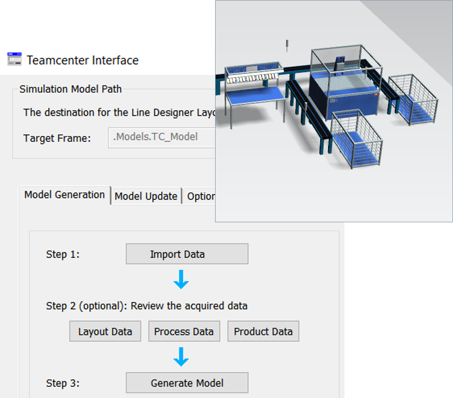
Creating 3D simulation layout from Line Designer layout
Interfacing between Plant Simulation and Teamcenter Manufacturing or Line Designer becomes easier and more powerful with the improved Plant Simulation configuration package for Teamcenter. In Plant Simulation 15, the Teamcenter Wizard supports and guides you to easily connect to Teamcenter. You can browse for simulation models or manufacturing datasets that have been prepared for use in simulation studies with Plant Simulation. The Wizard supports preparing the Teamcenter or Line Designer 3D layout as a basis for simulation models and can further be used as a starting point for the creation of customer or project specific interfaces. The Teamcenter Wizard does not create a complete, ready-to-use simulation model, as in most cases it will be necessary to define additional material flow logic and settings in those models. However, working Plant Simulation models with accurate layouts will be reached much faster using this enhanced interface.
Return to top. ^
PLCSIM Advanced 2.0 support and address access to PLC I/O
In virtual commissioning use cases with Plant Simulation and the PLCSIM Advanced virtual PLC from Siemens, the address-based access to data in the I/O memory segment of the PLC is now supported. This is an important enhancement in that when using the “i-Device Communication” pattern of the Siemens PLC, the symbolic names of Step-7 program variables cannot be used. Instead, you must use variable addresses in the I/O memory. This new feature of the PLCSIM Advanced interface opens many additional virtual commissioning opportunities while supporting state-of-the-art Siemens technology.
Return to top. ^
User experience enhancements and improved workflows
The manipulation of 3D object graphics is now supported via additional use cases for the blue manipulators. With these manipulators you can interactively scale and rotate your objects easily, just by a mouse click and drag operation. Pressing the “M” key on the keyboard displays the manipulators either for all objects or for all selected objects. The “M” key toggles the manipulator visibility – give it a try! We also introduced anchor points and manipulators for connectors in 3D, allowing for a user-controlled connector layout in 3D models.
Return to top. ^
Additional topics
Here are some additional changes that might be of interest for several project engineers working with Plant Simulation 15.
Plant Simulation now offers a simplified and direct assignment of an array with x-y-z coordinates to a position variable or attribute.
The automatic part processing on a station, which is the default behavior, can now be deactivated and you can start the processing through the command “station dot start Processing” (station.startProcessing) at any point in time later.
Using sensors on a conveyor as a destination setting for a pick & place robot simplifies the modeling of material handling robots next to a conveyor line.
You can now mark a palette as a “workpiece carrier”. With this setting, stations will work on a loaded part instead of working on the carrier. In many situations this is the intended behavior and you can now achieve it easily through a checkbox on the carrier object. And, we introduced a new button in the home ribbon to execute the default graphic optimization on the complete model by way of a single mouse click.
These are only a few of the many additional changes offered in this version. Many more enhancements and updates are documented in the “What’s New” chapter of the online help.
Return to top. ^
For complete details on the new features of Tecnomatix Plant Simulation 15, please refer to the release notes and new features presentation offered with the software download.
—–
(Don’t have Tecnomatix Plant Simulation? Try it for free here.)
—–
Yours in throughput optimization,
![]()
(on behalf of Georg Piepenbrock (@gepi) and the entire Tecnomatix Plant Simulation product team)