Ford automates factory layout design
Automaker shows how streamlined assembly line design helps to connect disparate systems and drive cost efficiency in manufacturing
The automotive industry, among others, suffers from disparate IT systems that make harnessing the value of data difficult. Connecting insight across products, processes, and people is an ongoing challenge. Even as digital manufacturing matures, integrating various digital threads is still elusive for many manufacturers.
Earlier this year, Jim White, a member of the Powertrain Manufacturing Engineering Digital Innovation Team at Ford Motor Company, presented their application of Line Designer in the Siemens NX™ software portfolio at Realize LIVE, Siemens’ worldwide user conference. This blog summarizes that presentation and shows how automating factory layout authoring is unifying Ford’s systems and driving cost efficiency.
The project
Ford Motor Company is a leading global automotive OEM with 186,000 employees worldwide (2020). Jim White is a powertrain manufacturing engineer and has been with Ford for over 25 years. He is currently part of the Powertrain Manufacturing Engineering Digital Innovation team and is responsible for developing and delivering new technical solutions and systems to make the job of engineering and delivering a powertrain manufacturing facility quicker, easier, and cheaper.
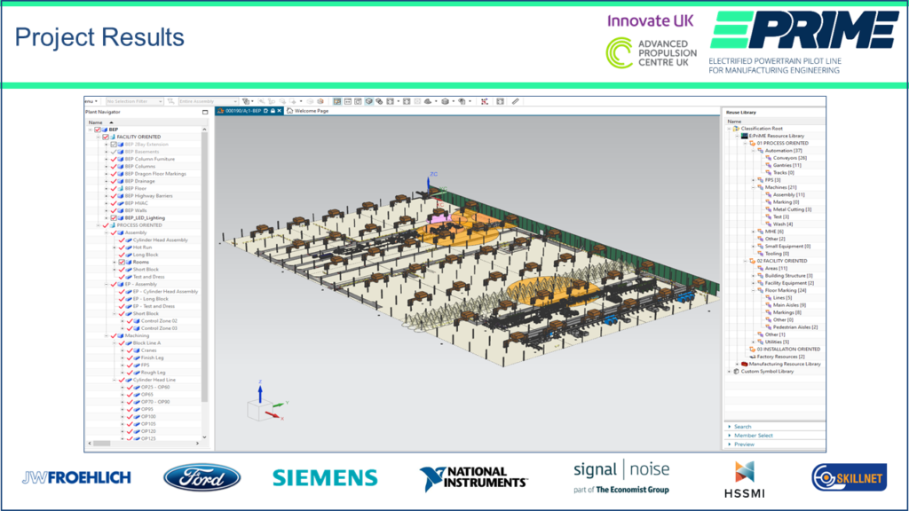
The work presented by Jim was made possible through the E:PriME project. E:PriME is a UK government-funded project with the aim of developing the UK industry’s skills in both electrified powertrain manufacturing techniques and digital tools that can be used to support the manufacturing engineering process. E:PriME consists of a consortium of 7 diverse companies of which Ford Motor Company is the lead member.
The challenge
Ford was facing the challenge of multiple, disconnected, legacy IT systems. In manufacturing engineering, their data was spread across these multiple systems, isolating different types of information, and often requiring duplication of data to be accessible within various systems. All this duplication takes time and is a primary source of error, with engineers often finding it hard to locate the correct data, and sometimes using the wrong data to make incorrect decisions.
The business result of these challenges was excessive time and cost. Often, problems that could have been found in the early phases of engineering design were not discovered until the physical equipment installation. That alone is a huge waste of time and resources; and was causing Ford to miss performance expectations.
The concept: bringing product, resources, and process together
The concept of the project was to unite product, resources, and process to eliminate the inefficiencies in disparate data systems. The “product” at Ford was the vehicle or powertrain design data; the 3D CAD models or 2D drawings or specifications which represent and define the vehicles, engines and transmissions that are manufactured at Ford.
“Resources” refer to the physical items that are used to build the product. Everything in a factory is considered a resource, from the basic building infrastructure (the floor, building columns, walls, roof structure, lighting, ventilation, offices, etc.) to the equipment and machines directly used to manufacture the product (machines, conveyors, gantries, robots, etc.). Resources include smaller equipment (like hand-held tools or power tools, small assembly fixtures, inspection gauges, etc.) as well as material handling equipment (stock racks, part transport dunnage, forklifts, tow tugs and trailers, lift assists and cranes, etc.). Anything you would physically be able to see or touch if you visited a factory is considered a resource.
“Process” is simply the set of instructions that must be followed in sequence to manufacture the product using the given resources.
Technology selection: NX Line Designer and Teamcenter
The solution selected by Ford used software from Siemens as a central, single manufacturing engineering IT system. They used NX Line Designer to author, or master, their factory layouts, and then linked these resource structures to existing product and process structures stored within the Siemens Teamcenter® software environment.
Teamcenter has been Ford’s primary system for managing product data for over 20 years. While two of the three types of data – product and process – are available in Teamcenter, historically resource data has not been managed there. Recent improvements in NX, specifically the Line Designer module, and its performance in loading and manipulating large quantities of 3D data have made proper resource management in Teamcenter possible. Teamcenter continues to handle the key requirement of change management and is a full-featured data management system.
Project objectives
Ford’s primary goal was to develop the methods needed to effectively author their plant layouts, or resource structures in Teamcenter. They wanted to understand how Teamcenter change management techniques could be applied to their structures, and to ensure those structures were designed to allow different engineering teams to make most effective use of them. They also wanted to ensure they could easily link their new resource structures to existing product and process structures.
It was also important to Ford to gain an understanding of how CAD data from their equipment suppliers – both legacy and future – could be used and understand how to create their own CAD when required. They wanted to investigate how to compare CAD with real-life physical equipment using laser scans and point cloud technology. They also needed to export data from Teamcenter / NX in AutoCAD format to support some downstream legacy processes and teams who have not yet been able to move into the shared Teamcenter environment.
The solution
With NX Line Designer and Teamcenter, the Ford plant facility was viewable, including engine assembly, cylinder block, and cylinder head machining lines, together with a myriad of factory equipment, with good graphical performance.
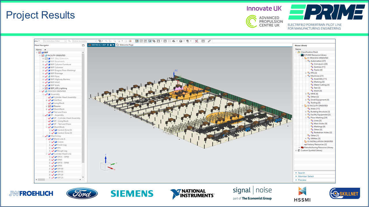
In Teamcenter, Ford organized their factory layout structures by splitting their resource data into two categories. First, facility-oriented data, which relates to the physical fabric of the building – floors, walls, lighting, drainage, aisleways, etc. Typically, this type of resource does not change very frequently. Second, process-oriented data, which includes all the resources more directly involved in the manufacture of a product – the machining and assembly lines.
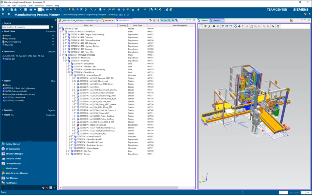
With the plant structure then loaded into NX Line Designer, the facility is viewable in 3D and 2D, allowing the view to be de-cluttered. The data load time from Teamcenter was very good, on the order of minutes for large data sets.
The users were able to display various parts of the engine assembly line, toggling between 2D and 3D as necessary, with good graphical performance. Using the 3D working environment, issues become much more apparent, such as the reach distance of a fire hose on the central building column being impeded by a floor conveyor nearby. Lighting can me modeled with cone floor circles, revealing gaps in coverage. Ultimately, the user can switch quickly and easily between different reference sets, depending on what task they are trying to perform.
Line Designer can segment the factory into a grid, allowing the user to load single squares or multiple squares, each containing all relevant resources. This capability suits different use cases and reduces the amount of data required to be loaded.
Line Designer can also handle point cloud data, directly overlaid with CAD data. The Ford team was able to bring their resource structures together very easily with 3D CAD and laser scan point cloud data. Immediately, they were able to identify errors in the 3D CAD. These errors were mostly items missing from the resource structure, but there were also slight differences in the equipment CAD. The user was able to remedy each problem to improve the overall quality of the 3D CAD models and the completeness of the whole resource structure.
The Ford team was able to successfully bring together product, process, and resource data automatically from Teamcenter, overcoming a long-standing problem of simulation engineers having to manually re-create a factory layout in the simulation environment. Previously, that recreated factory layout was not linked to the master factory layout, so changes in the layout would need to be manually synchronized into the simulation – a very inefficient, time-consuming, and error-prone process.
With NX Line Designer, factory layout nodes come directly from the master Teamcenter factory layout resource structure. The simulation engineer can simply concentrate on performing the actual “study” of the assembly station, knowing they are using the correct master factory layout data. Now the team can simulate many more stations in a given time, as much less time is spent on administration (e.g., building the study).
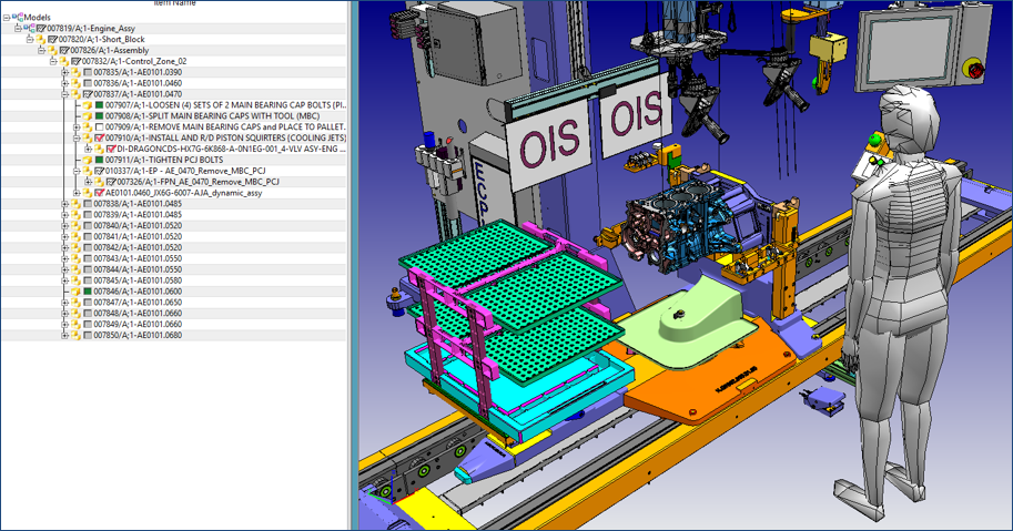
Finally, the team was also able to export a resource structure to AutoCAD, including the facility-oriented data (e.g., aisleways), together with process-oriented data (e.g., the engine assembly line and cylinder block machining). That capability proved that Ford can correctly support all downstream processes, or external vendors, who continue to rely on AutoCAD as a format.
The results
This proof-of-concept project at Ford successfully validated their desired state. The existing plant layout was re-engineered in Teamcenter and NX Line Designer. All key types of facility / process data were included. They used both existing CAD and new 3D CAD, and visualizations were created and used. Plant resource data could be viewed in facility position, or product position, and used by 2D and 3D views alternately. They were able to overlay laser scan data, export to AutoCAD, and use Teamcenter’s change management to allow alternative layout proposals, time-based equipment installation plans, formal layout release approvals, and vendor CAD maturity.
Ultimately, the Ford team was able to eliminate some of their disconnected engineering IT systems that were driving data duplication. In turn, they were able to decrease engineering cost and instances of late identification of issues related to equipment design and installation. Ford is planning to roll out this work to the wider powertrain manufacturing engineering teams and pilot their methods and techniques on various programs.
—–
> To hear more customer success stories like this one or to share your own success, join us at Realize LIVE.


