Working with imported data to reduce design costs
In today’s world it’s very rare for an entire product to be designed within a single CAD system. Getting to market quickly requires the development process to be as efficient as possible, and often means outsourcing specialist engineering tasks such as finite element analysis (FEA). Sharing information with a variety of suppliers, partners and customers is essential. And for smaller firms that deliver these professional services to other companies, the requirement to import data, make cost effective modification and repairs is even more important.
 TOP-TECH – provide professional services such as plastic injection mold analysis to major manufacturers have little or no control over the CAD files they receive. Being able to edit, repair and simplify models in a single system is essential for providing cost effective ‘value added’ engineering to their customers. Image courtesy of TOP-TECH, Poland.
This is particularly true when considering design reuse for engineering work such as FEA or machining, milling and turning. Every engineering organisation likes to reuse designs especially 3D models. It allows them to take already completed designs and quickly repurpose them into next generation products or use for further engineering, avoiding having to start from scratch and duplicating previous efforts.
However, design models with hundreds of interrelated features can be very difficult to change and models don’t always translate cleanly. This is further complicated by a lack of interoperability, which means it’s difficult to edit files without a multi-CAD environment, this is both very expensive and requires designers who can operate every system.
A challenge arises bringing all these models and information together into a single file without losing or recreating work. These factors all contribute to needing to work effectively with imported data. New CAD technologies offer solutions that enable companies to design better, import data from other CAD systems easily and adapt geometry effectively while maintaining design intent.
The challenge
As mentioned, product development is not done in isolation. Many engineering firms, particularly smaller ones, specialise in delivering professional services such as finite element analysis (FEA), Mould Design or computer aided manufacturing (CAM) to other companies.
Many of these firms don’t have the financial resources or multi-system expertise to work in a wide variety of CAD systems, at the same time they have little or no control over the 3D data sources that are provided to them, but still need to modify designs. They may need to remove small features and holes that slow down analysis calculations but don’t impact strength.
Because all CAD systems store data differently, without owning every system and having the skill to operate them, making changes for additional operations is difficult – unless you can manipulate the 3D geometry directly. Essentially, not only do you need to be able to import the data into your existing CAD applications, you also need to be able to modify, repair and make changes easily – most systems don’t make the latter part of this process easy.
Ultimately, importing 3D models isn’t really the problem, but because proprietary information, such as feature trees, dimensions and properties are often lost in the translation, these imported designs usually lose important design intent. This makes it difficult, or even impossible, to manipulate models for tasks such as alterations, repairs or de-featuring. This challenge is exacerbated by the growing drive to develop concurrently, when models are constantly being altered and the revised versions shared amongst other stakeholders (such as FEA).
As a result, the most important thing is to be able quickly edit featureless geometry when changes are required easily.
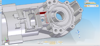
 Moving 3D models from one CAD system to another does not always translate cleanly. Solid Edge’s geometry inspector identifies faults such as small faces, spikes and slivers based on set tolerances. Synchronous technology is used to make fast repairs before additional work is carried out. Image courtesy of TOP-TECH, Poland.
In fact, according to a survey by research group Aberdeen, almost half (44 per cent) of 3D users worry about being able to reuse existing data from previous designs, suppliers and customers and most companies stated that the ability to work with third party data was one of their top five challenges.
 Synchronous technology works directly on 3D geometry so repaired models or files imported from other CAD systems can be efficiently edited as though they are native Solid Edge files. Image courtesy of TOP-TECH, Poland.
Importing legacy data
There are several ways of importing non-native data from other CAD systems, but they all have their limitations, leaving users to pick the least-worst option for their particular circumstances. The best is to be able to use a native file, but unless you have multiple CAD systems this is not possible.
Another option is to use industry standard neutral file formats such as DXF, STEP or IGES. These are the least expensive and the most compatible way to transfer data, but they are not the most reliable, sometimes lacking faces, surfaces, solids or other aspects. Furthermore, because they only include the shape geometry and graphics (dumb solid), they lack attributes like features, dimensions and parametric constraints making changes to original designs very difficult after translation – unless your system can deal with this.
A more reliable way to share data is to use the geometry directly from the modelling kernel using Parasolid (X_T) or ACIS (SAT) formats, however this is not always possible as most other CAD systems use their own proprietary kernels.
In between these extremes lies the area of direct translators. As the name suggests, these translate files from one system to another, and are useful for transferring data between different CAD systems, but still lack any feature information.
Other technologies such as direct editing or feature recognition are available to help once geometry is imported, but don’t provide a complete solution.
Without control over the source of data it takes a lot to modify the original geometry, there is a real industry need for a modelling approach that can modify data no matter where it came from.
File formats and modelling technologies
Each system has different ways of storing the data that describes how a 3D model looks and behaves. These data streams can store information such as the geometry itself (from the kernel), the visual display, dimensions, features, relationships, properties and many other attributes. While some systems may share the same kernel, the way it stores these data streams is different. Usually only the geometry, display and colours survive when transferring data from one system to another. So you end up with a dumb solid that’s hard to edit freely.
There are also different modelling technologies too. History-based systems are dimension driven and take advantage of ordered features and parametric constraints. This makes them highly automated, but these systems require a lot of preplanning to avoid unpredictable results while making changes later, performing edits on third party files is very difficult.
On the other hand, history-free modellers can be easier to use and more flexible. They are better at interacting with geometry directly, but they don’t maintain design intent very well. These history-free modellers allow users to push and pull on surfaces to make changes, but are featureless and lacking in design automation, making later changes time consuming as multiple edits are required.
Both modelling systems have their place – history-based systems lend themselves more to a production environment where precise predictable changes are required, while implicit modellers are better suited to conceptual design work when form is more important than function.
The best of all worlds
Having identified the limitations of different import and translation techniques and the strengths and weakness of both history and history-free models, the Holy Grail is to find a way to marry the strengths from both of these design methods.
The combination provides the speed and flexibility of history-free modelling with the precision and automation of history-based systems. This allows user to create designs without pre-planning, using dimensions and features to develop highly automated designs, while getting fast performance during edits.
Amalgamating advantages of both systems means designers can modify the geometry by pushing, pulling and rotating faces precisely or adding 3D driving dimensions to lock in design intent no matter where the data came from. This is called synchronous technology.
 Selecting geometry on imported models that lack features is tedious and time consuming. Solid Edge’s Selection Manager is able to find and select geometry based on geometric conditions enabling users to work on imported models as though they are native models. Image courtesy of TOP-TECH, Poland.
By modelling with synchronous technology it becomes possible for companies to make edits to models in-house with a single system more easily than the software that created them.
 3D driving dimensions allow design intent to be reestablished on 3D models with minimal effort, while ‘Live Rules’ removes the need for feature dependencies by maintaining geometric conditions such as concentricity, tangency, co-linear and co-planer faces. Resulting in lightning fast edits to 3D models no matter where they came from. Image courtesy of TOP-TECH, Poland.
Conclusion
There is no uniform convention for CAD files and 3D models across different applications – or even across platform versions – leaving designers with a wide number of models across a variety of formats.
An incumbent CAD system may be effective on native files, but making realistic modifications to other 3D models is where most companies struggle with a lack of functionality from their CAD system and making edits or integrating parts into existing designs is where the challenge is.
While there are a number of import and translation tools available, each of these has their shortfalls and drawbacks and often remodelling is required and this means wasted time, money and resources. Both history and history-free modellers provide a modicum of ability to change imported data, but they don’t provide a full solution.
In order to help overcome these challenges, Siemens developed Solid Edge with Synchronous Technology to marry the best of both worlds, enabling companies to design better and import data from other CAD systems easily and adapt geometry effectively while maintaining design intent. The Live Rules functionality automatically finds and maintains geometric conditions within the 3D model, even recognising those lost during translations. For instance, imagine selecting a single face and having the tangent blends and collinear wall thickness automatically update at the same time.
This combination eliminates the need to pre-planning and reduces the learning curve, while allowing for faster revisions and the editing of geometry regardless of feature creation order even if features don’t exist.
In a world where importing data is vital for a host of reasons, this approach helps to accelerate the design process and reduce costs by allowing imported data top be edited as if it was a native model.


Comments