What’s New in ST10: Reverse Engineering

One of the components of Convergent Modeling is Reverse Engineering. It encompasses a new tab in the Solid Edge interface that also includes the Select and Plane tools as well as Curves and Surfaces. The idea behind Reverse Engineering is that you can take 3D scan data in the form of an STL file, clean up the data, group face types by color, and then create faces over the selections. Finally, you use surfacing operations to enclose a solid. There are automated and manual options so that you can always get your work done.
If you’ve done any reverse engineering from mesh files previous to this, you know what a pain it can be, and these Solid Edge tools are the first step in simplifying the process.
3D scanning never gives you CAD-perfect data, so the ability to massage the mesh is critical. The scan below shows a part I got from community member and Solid Edge user Craig Hall of Hall Designs. Craig scanned this machined part and the data is mostly good. Scanning interior pockets often doesn’t produce perfect results. You can see there are partial faces and missing faces on the back side. There is enough data to recreate the faces you need, but there is enough missing that you’ll have to work for good results.

This Reverse Engineering functionality was previously an add-in in beta, and it has been blogged about before by Sandeep Mamdapur. I’ve borrowed some images and information from his blog post, but that post is still very relevant, and I suggest you go back and read it, although some of what Sandeep had to say pertained only to the beta. The functionality in ST10 is installed with the main download of the software.
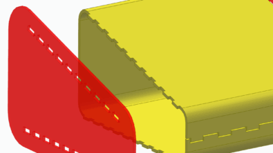
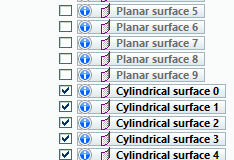
The image below is the result of the Automatic command, which identifies the regions. A legend for the colors is available in the Help, but you can see the big planar regions are yellow, the cylindrical holes are cyan. The fillets here are identified as freeform. Applying fillets to the final part will be easier than the rest of the job, and the fillets should be applied as ordered features after everything else is done.
I should probably point out that the result of this process is a set of surface bodies, so they are better off in Synchronous mode. Once the model is finished, any of the analytical type faces can be edited with normal Synchronous tools. Freeform faces cannot at this point be edited Synchronously.

Also, you should make sure to get the main body oriented the way you want it with respect to the part origin. Scanned parts are a bit notorious for coming in at odd angles.
Once you have identified the areas to be recognized as various analytical types the next task is to extract the surfaces. If you used the Automatic region identification, you can use the Extract command to automatically extract faces that have the standard colors identified in the legend above. Any faces where you have used custom colors or Manually identified regions will require the Fit command.
You can do this process iteratively so that you create the surfaces needed to build one section of the model, perform the surfacing operations, and then go back and extract the surfaces for another section of the model.


 Once you have the needed faces created, you can use the standard surfacing commands (including Intersect, Trim, Extend, Stitched) to begin to enclose the shape. You can also use Intersection curves to capture sketches used to extrude more surfaces, or any other surfacing technique.
The more analytical type faces you use in completing the model, the better the model will respond to Synchronous editing.
If you have ever worked on reverse engineering projects, you can appreciate how much time this can save you, especially considering that when you’re done, you’ve got something that Synchronous Technology can edit fluently.
The Reverse Engineering functionality is included with the following levels of the software:
- Solid Edge Premium
- Solid Edge Classic
- Solid Edge Academic
- Solid Edge AcademicU
With all of the new tools in ST10 brought to us with Convergent Modeling, working with mesh data is becoming easier and easier. Considering the proliferation of sources of this type of data in the last several years, Reverse Engineering will be a welcome addition to the toolbox of many Solid Edge users.
Stay tuned, you’ll find more info on What’s New in ST10 here on this blog.