Using Lookup Tables in Solid Edge
Before the advent of computers, lookup tables of values were used by people to speed up hand calculations of complex functions such as in trigonometry and logarithms. In ancient India (499 CE), Aryabhatt created one of the first sine tables, which he encoded in a Sanskrit letter based number system.
Every design department has its own variety of look up tables for use in modern engineering calculations. Some common uses of lookup tables are:
1. Defining the various dimensions of pipe and conduit fittings based on the nominal diameter of the fitting.
2. Keyway sizes based on shaft diameter.
3. Inch to mm and vice versa conversions for standard values.
4. Various part catalogs.
and all those tables from the various machine design hand books.
Lookup tables need not be always be numeric. There are lookup tables to determine the type of components to be picked for assembling based on a particular product type.
A Lookup Table has three main parts:
1. Reference column.
2. Lookup value.
3. Lookup column(s).

As use of computers proliferated from large business houses to smaller manufacturers, spreadsheets were adopted more commonly later followed by CAD programs. This article describes how to harness the best features of both spreadsheets and CAD to drive a parametric part in Solid Edge from a lookup table in Excel.
This can be accomplished in three steps:
1. Create a table in Excel and add lookup intelligence using the VLOOKUP function.
2. Create the parametric part in Solid Edge and setup control variables.
3. Link the output of the lookup table i.e. the lookup values to the controlling variables in Solid Edge.
Step 1
Creating a 3-column table in Excel for shaft diameter, keyway width and depth doesn’t need much explanation. preferably color code various cells and columns so you can follow the next few instructions easily.
The next step is to build the lookup functionality. The goal is to automatically pick the keyway width and depth values into the orange cells from their respective column by typing the shaft diameter in the light blue cell at the bottom of ShaftDia column.

Click inside the orange cell at the bottom of column KeywayWidth and from the ribbon select Formulas > Function Library > Insert Function.
The Insert Function dialog appears. Select ‘Lookup & Reference ’ from the category dropdown and choose VLOOKUP from the list below. Click OK. A dialog box pops up. For ‘Lookup_value’ click the dark blue cell under ‘ShaftDia’.

For the Table_array, select across the entire pink and green columns as shown below.
 For Col_index_num, type 2 since KeywayWidth is the second column in the selected table range.
Similarly, setup the vLookUp for the KeyWaydepth orange cell at the bottom by repeating the steps above and specifying Col_index_num as 3 since this is the third column in the selected range.
For Range_lookup, type False in both cases and the Lookup table is all set. Try changing shaft diameter in the blue cell to one of the values in the column for shaft dia.
Note that the table, by virtue of its newly acquired intelligence, updates the orange cells for keyway width and depth automatically to the corresponding values from the columns above them.

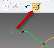
Step 2 Create a simple shaft in Solid Edge by extruding a dimensioned circle. If you are on ST7, can use the cylinder primitive. Make sure when dimensioning the circle, the diameter option is selected on the Command bar.
Also create a keyway and dimension its depth and width, All these dimensions reflect in the Variable Table. Right click in an empty space in the graphics area and select Variables…
Select each variable and rename it by pressing F2 followed by typing in a more meaningful name such as KeywayDepth, KeywayWidth, etc.
Step 3 The final step is to link the blue and orange cells to the Solid Edge model. Link all three values – one for shaft diameter and the two looked up values. This part is already explained in detail in this article.
Arrange Solid Edge and Excel side-by-side by right clicking on the Windows taskbar and selecting this option. Then simply change the lookup value for shaft diameter in the blue cell and marvel at the corresponding values picked up automatically. The beauty of this feature in Solid Edge is the model updates in real-time without having to click an extra update or refresh button.
There is practically no limit to the number of columns that can be used.
And not just that, you can:
• Use tables from across multiple sheets to control a part.
• Use tables from across multiple Excel files to control a part.
• Use a single table to control multiple parts.
In short you can link multiple part or assembly files from multiple tables in multiple sheets, in multiple excel files located on multiple computers on your network !