Techniques to Use Solid Edge Features to the Fullest
Prolog
Last month Solid Edge University was organised as part of the bigger Siemens PLM Connection event in Phoenix, Arizona and the temperature outdoors soared past 100 F. People soon lined up in front of roadside ice-cream stands to pick from a variety of flavors and colors with choice of cream and sprinkles. They were all served in a cone or a cup which again was a frustum of cone. Soon an interesting discussion sprang up about the number of ways a cone or frustum could be modeled in Solid Edge.
Whereas revolved protrusion and using the Draft command to create a taper on a cylinder were no-brainers, someone pointed out that extruding a circle in the ordered mode has a special draft treatment option on the Command bar which applies a taper on the extruded cylinder creating frustum of a cone.

Attempting to think differently, a person still undecided about choosing a waffle or sugar cone, recommended lofting between two circles, while a product designer who played with surfaces as part of his day job opted for creating 3 surfaces and stitching them up.

Yet another person travelling from the far east advocated scanning an existing ice-cream cone and tweaking the mesh model as required. I was like ‘bring it on…’ for Solid Edge with convergent modeling capabilities can handle it gracefully and enhancements in Solid Edge 2019 further create smoother meshes, besides stitching mesh surfaces, replacing mesh faces, detecting and deleting fillets and chamfers in scanned mesh bodies to sharp edges.

It is also possible to move and rotate mesh geometry using the steering wheel in addition to cut, copy, paste and attach mesh bodies.
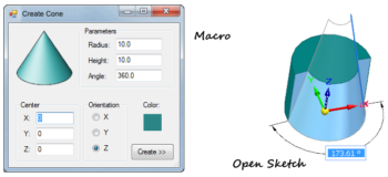
As a Solid Edge app programming specialist I offered to write a free macro that would pop out a cone with parameters specified via a dialog box. But if I were to model it manually, I would place my bets on an open sketch – a single inclined line revolved about a cylinder axis to get the job done in a jiffy, a simple, elegant and uniquely powerful feature of Solid Edge. Having used this technique about 18 yrs back, it is my favourite and currently also available on my modern Solid Edge blog.

Before long, we had amassed an astonishing 8 distinct methods just for creating a simple cone or its frustum. Sheer joy for Edgers who were spoilt for choices just like their ice-creams and cones, but more noticeably each one admitting being completely unaware of 5-6 of those methods. Walking back to the convention center, I pondered what could possibly keep people from exploring other options which were hiding in plain sight.
The reasons could be many. On-the-job self-learning being the most prominent, where they were perhaps thrown a design, left to twiddle with Solid Edge and as new learners somehow figured out how to get the job done while also meeting the deadline.
If it was instructor-led training, perhaps they were shown just one technique and left with the rest for homework, which they could not complete eventually.
Yet another reason could be switching over from other CAD to Solid Edge, one that was a 2D drafting program where options are limited, especially for creating 3D objects.
This prevents users from discovering and effectively using powerful commands in Solid Edge that have no equivalent in other CAD programs. Long story short, if you are creating some parts of your designs using the same method repeatedly you are using Solid Edge inefficiently.
More Techniques
The cone analogy may sound over-simplistic but if you are not exploring alternative methods in Solid Edge you risk being stuck up in using suboptimal strategies to perform certain tasks.
Although these suboptimal strategies do not necessarily prevent you from producing clean and accurate models or drawings, the inefficiencies tend to remain unrecognized and you end up having little motivation to develop better strategies.
The efficient use of Solid Edge demands the use of strategies that take advantage of its capabilities. To understand why even experienced users do not have this strategic knowledge, lets take the example of assembly creation, particularly the process of placing additional occurrences in assemblies where you’ve got no less than 11 options at your disposal depending on the task at hand.
- Drag-Drop from Parts Library – if you have a well thought out folder structure.
- Drag-Drop from Windows Explorer – take advantage of a dual monitor if you have.
- Drag-Drop from the assembly PathFinder – if you already have a part or assembly inserted.
- Copy-Paste existing components.
- Ctrl+Drag a part or sub-assembly from the graphics area to insert another instance.
- Mirror.
- Circular and Rectangular Patterns – take advantage of the pattern created in the part.
- Pattern along curve – a powerful tool and a logical extension to (6).
- Duplicate Component – Introduced in ST7 this command also auto-orients to match that of the mating parts in the assembly.
- Clone Component – to place multiple occurrences of components at different locations in an assembly based on geometry recognition. This hidden gem is artificial intelligence built right inside Solid Edge.
- Inter Assembly Copy – insert an associative copy of an existing assembly file into another assembly. Super user @KennyG has written a neat and concise blog article about this feature.
Knowing such multiple features in Solid Edge can assist in reducing the number of steps to complete certain tasks.
The trivial task of issuing commands in Solid Edge is another example. When the Fluent interface was introduced in Solid Edge ST, most long-time users were scathing at the new style of initiating commands and the ribbon tab. This was soon followed by several new facilities like the Quick Access Toolbar or QAT and the Radial Menu, all of which were customizable from the word go, unlike the pull-down menus of previous versions.
The God of Solid Edge @dcstaples recommends and with great tenacity outlines the steps for customizing the radial menu to enable you accomplish virtually any design task in Solid Edge, and rightfully so.
Keyboard shortcuts too are customizable but best used in combination with other methods. Lastly, don’t forget the Command Finder which is permanently stationed at the bottom of the Solid Edge screen. This feature is highly recommended if you are new to Solid Edge and need to start a command you haven’t used before.
Epilog
Every new release brings in hundreds of new features and enhancements. Whereas Solid Edge is prolific in terms of the features available for accomplishing seemingly similar tasks, such strategic knowledge to use Solid Edge effectively is neither defined nor explicitly taught. The advantages of these commands and features are not for free. They come at the expense of having to explore the software which could take an indefinitely long time. So making best use of available resources and interacting with fellow users is highly recommended.
Forum participation, attending Solid Edge Universities, reading Tips & Tricks, watching YouTube videos, subscribing to high quality blogs like this one by the Solid Edge maestro @Imics , browsing the Solid Edge Knowledge base after having completed the plentifulonline tutorials provide great avenues for gaining new knowledge and endless opportunities for serendipitous discoveries of efficient strategies, complimenting your many years of experience.