Surfacing: Techniques from the Trenches
Solid Edge surfacing is an area which can be conquered only by getting your hands dirty.
There is no way mastering it by marveling at designs created by others or by reverse engineering it in terms of the commands that might have gone into making them.
The techniques illustrated below are aimed to invigorate both new and experienced users.
Clay Model Analogy
Create larger surfaces first. Just as in clay modeling, where you would work with your largest tools first, build your CAD model by creating the largest surfaces first.
Analyze your design concept and determine the largest features and surfaces and try to create those first. Leave the smaller details and features for last. Take the example of a hair dryer model below.

There are three distinct parts to it. The top one is the blower casing, the second is the handle and the third one in the middle is the joint between the two parts.
It is possible to create them in the order : casing-joint-handle. In this case, it is recommended to create the blower casing and the handle first, since it establishes the relative position and angle between the two. The smaller detail like the joint can then follow.
Use Birails for a Jumpstart
When the design is relatively simple, try to visualize a given surface as two cross-sections and two guide-curves called birails. A BlueSurf can then be fitted using just these four curves.
The birail method allows you to quickly get to the overall form of your design with less of curve
creation. See the bottle in figure and its four curves. Similarly, a door knob with complex looking organic shapes can also be created quickly using just four curves.
Blend Modeling – Best of Both the Worlds
If you peep a little deeper into the history of CAD, it were surfaces that were invented first, then came along the solids. In Solid Edge, both surfacing and part modeling commands sit side-by-side in the Part environment.
Tools from both tabs – Home and Surfacing – can be used in conjunction to create a single part. This type of modeling practice called Blend modeling – use it to your advantage – there is no harm in using a concoction of all known curve and surface creation commands in Solid Edge.


The mouse shown in the image is an example of Blend modeling at work. Curves were used to to create the orange surface. Similarly Curves were also used to create a base protrusion. Using the Replace Face 
By combining a solid and a surface together, you can form a hybrid model to obtain a desired shape without needing to build it with surfaces alone.
Think Global – Act Local
Needless to say, curves play an important role in the final appearance of a surface and of the product. So think global (about the form of the final surface) and act local (pay attention to the curves).
When tweaking curves, it is often required to move the control points. When doing this, the endpoints of the curve may go haywire, affecting the desired shape of the curve.
To keep the end points in place, you may apply the Lock relationship to the endpoints of the curve.
Another powerful feature that Solid Edge provides is the Local Edit option available on the Ribbon bar when you select the curve (see the right figure).
By turning this option ON, only that part of the curve lying between the two control points adjacent to the control point being edited is affected.
The beauty of this option is that the endpoints stay in place even when you are editing the second control point from either end on the curve even without a Lock relationship applied.
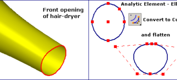
Start with Analytic Elements
Based on the design, try to imagine the curve you want to draw as one morphed or closely resembling a cricle, an ellipse or even a rectangle. In such cases start with an analytic element like a circle, an ellipse or a rectangle.
Further using the Convert to Curve 
Take the example of the hair-dryer. The front end opening of the hair-dryer is a closed curve.
Here, an ellipse (an analytic curve) is first created. Then, using the Convert to Curve tool, it is converted to a curve where the shape remains the same as that of an ellipse.
More control points can be added from the Command Bar using the Add/Remove Points 


Then by simlpy dragging the control points, the top and bottom parts of the ellipse are flattened to get the desired shape.
And yes, even a rectangle can be converted into a curve using the Convert to Curve. Start the command and pick the four sides of the rectangle one after another and each is converted to a curve with the endpoints still connected – thus saving you lot of work.
Garbage In – Garbage Out
When creating curves, it is always recommended to use lesser number of control points on the curve. Not any more with Solid Edge. Start out with a curve having as many control points as you wish.
You may again use the Add/Remove Points option on the ribbon bar when a curve is selected. Tweak the curve to your heart’s desire. Once you are satisfied with the shape of the curve, right click on the selected curve and select Simplify from the menu.
Adjust the tolerance value in the dialog box and keep a watch on the current number of edit points and control vertices. Click OK when done. Now you have a much lighter curve. The Tolerance value determines how much detail and accuracy a curve and a surface will have.
Visualize tolerance as a tube. The original curve is at the center of a zero diameter tube. As the tube diameter (tolerance) increases, edit points are reduced as the curve shape is confined to the tube diameter. As the tolerance increases the curve is simplified.
This way you can have more control points to begin with and still end-up in a much lighter or non-heavy curve with a close-to-desired shape, since simplification may affect the shape of the curve to some extent, but within acceptable limits.
Also, this will ensure a smoother and geometrically clean surface.