ST6: Emboss
 The Emboss feature in ST6 may be a sleeper, but I’m pretty sure there are going to be a few of you that realize what a beautiful thing this turns out to be. The first thing that’s really great about it is that you can use it either on sheet metal or on regular parts. On sheet metal parts, you can use it for form across bends. In regular parts, you can find Emboss in the Solids > Thin Wall area. So this feature can be used for castings, injection molded parts, pressed/drawn/forged parts and more.
Like a few features in Solid Edge, this feature leads a double life. In Synchronous, the results are the results, and you deal with them synchronously. It’s just geometry, and as long as the faces are not spline-based faces, you can edit them with Dimensions, Face Relations, Steering Wheel, and Live Rules.
In Ordered, the feature uses a body (that acts like a stamping die) to do the embossing, along with a set of parameters established in the feature.
 So you can start with a flat sheet of material, insert a part copy, and emboss the flat sheet with the
  imported shape. You can take an existing part and build a new body, and use the body to create a thin walled area with some gap between the body and the embossed shape.
Building thin walled parts can be difficult stuff if you’re just using the regular tools. Good thin wall requires either the Thin Wall feature (called Shell in other popular packages), ribs, or sheet metal tools. The Emboss feature is almost like cheating, its so easy.
The best way to show this is with an example. I’ve got a Solid Edge part attached to this blog post you can download as a starting point if you’d like to work along with this example. The part you start from is called plasticpart.par. The finished part for reference is called plasticpartemboss.par.
This is going to use a little multi-body mojo. Multi-body functionality was greatly expanded in ST5, maybe in part to make way for features like this. I’m going to write about multi-body functionality in greater detail in a dedicated post later on, but for now, if you don’t already know how to deal with them, I’ll give you what you need to know to get through this example.
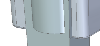
 In this case, we are starting out with a simple plastic part, shown above in section. A change must be made to the plastic part that any design intent could not have anticipated. Going back to change history-based features is not the way to make this kind of change, and the method of direct editing is also not going to work. Instead, I’m just going to apply the change right over the top of some of the existing geometry to merge the change with the existing part more simply than you might expect.
The forming die has already been brought in and positioned for you, but if you want to practice doing that for yourself, download the attachment called tool.par, and put it somewhere on your computer where you can get to it. Next, use the Part Copy command. This is found on the Home tab, in the Clipboard group. There is a picture of the icon earlier in this blog post. It’s up to you whether you want to do this in Synchronous or in Ordered mode, depending on where you are most comfortable making your changes.
Next, browse to the downloaded tool.par part, and just click OK in the Part Copy Parameters box.
 The body doesn’t come in positioned correctly, so you have to move it. You should see a Construction Bodies collector in the Pathfinder above Synchronous. Click on the body in the collector and use the Steering Wheel to move the body approximately as shown below. The easiest way to use the Steering Wheel is to just pull on the arrow in the direction you want the body to move.
Also you may notice that the body shown is not as wide as the one you will bring in through Part Copy. To change the width, clear the selection by pressing ESC, then select one of the side faces and push the Steering Wheel arrow in the correct direction. Do that for both sides. I didn’t use dimensions for this rough example, but if freewheeling it bothers you, you can use as many decimal places as you like ;o)
 Further, notice that the Part Copy body is colored. Here’s how I handle that (and I actually recommend a transparent color for this application). Clear the selection, go to the View tab, and in the Style group, pick on the Part Painter icon.
Set the Select option to Body, and the Style to Green (glass) or something to your liking. Then pick on the tool body. When you close the Part Painter, you should see the body in the new color.
 Next, to use the new body to Emboss the part, click on the Home tab, the Solids group, and use the Thin Wall flyout, to select the Emboss icon.
 The Select Target Step should be highlighted, so select the main plastic part. Now the Select Tool Step should highlight, and you can select the tool body. If the preview shows a chunk taken out of the part instead of an area built on, click the Direction button.
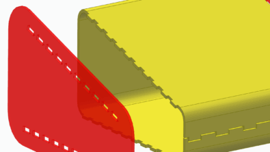
The tool can either “indent” the part or “outdent” it, to take some liberties with the language. If you are using Synchronous, you’ve got to make this decision right up front. If you are using Ordered for this feature, you can change your mind later on. (This is part of the power of mixing modes).
As a part of the Emboss process, you can set the thickness of the material, which in this case is 0.08″. You can also set a clearance gap, so that if the tool actually represents a motor or some electronics, you can create an air gap around the parts.
The image on the left shows the “indent” and on the right is the “outdent”, just for reference.


If you wanted to, you could have added rounds to the tool body, so the plastic part would have rounds already on the inside and outside. If you didn’t do that, then you’ll have to add rounds manually (remember to apply them to the inside corners first, then outside corners – this does not always mean the inside and outside of the part – rounds on inside corners add material, and rounds on the outside corners remove material).
Remember also that Emboss is a tool that can be used on sheet metal or regular parts. Any time you have a thin walled anything, you can use this tool.
And that, my friends, is the magic of the Emboss feature, new for your plastic and sheet metal pleasure in ST6.


Comments