Sheet Metal Tour: Hems
 The next stop on our tour of the sheet metal functions in Solid Edge is the Hem tool.
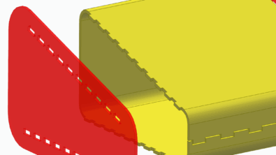
Hem is just meant to fold over the edges of parts usually for safety, aesthetic, or strength issues.
 The first line of the Hem Optionsdialog allows for saved settings. So if you set up a hem you like, you can save the settings with a particular name, and the next time you want to create another hem with the same settings, you can just pick the name from the drop down list. For example, the CommandBar is shown in the image to the right, and the drop down arrow next to the Hem Options icon allows you to quickly select saved hem settings from the list.
The entire Hem Options dialog is shown below. The hem types that are available from the list are:

Closed, Open, S-flange, Curl, and Closed Loop, respectively. A small complaint about the drop down selection list is that it would be easier to use if all the images were presented to the user at the same time, as above. This would mean 10 fewer clicks (because you have to click the arrow and then the option to see what it is) when you use it. Sure, the dialog box would take up the whole screen, but you aren’t using the rest of the screen anyway.

There are severalstrategies for setting up interfaces: save space, speed, clicks, mouse travel, or “discoverability” (ease of learning). These strategies are usually at odds with one another to some extent, so it’s impossible to satisfy all the strategies at the same time. The Solid Edge interface in general is an incredibly space-efficient setup, especially considering the CommandBar and things like the Marking Menu. Drop down menus are also very space efficient, but score lower on the other UI concerns such as speed or clicks or learning. The radio buttons shown in the bottom half of the Hem Options are better for speed and learning, but take up more space, especially when there are more than a couple of options. I like my Solid Edge interface setup with more text on it which makes it less space efficient but easier to learn.
Again, the Bend Relief area on this dialog is not labeled. I guess it’s not a big issue, but one might wonder what all the Square and Round illustrations are referring to.

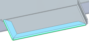
The Miter Hem option gives you the ability to make a mitered hem as shown here. The blue faces are part of the hem.
These options are powerful andmore complete than what I’ve seen in other software.
 The only remaining setting for the Hem feature is the Material setback. The icons and descriptive names seem to do a good job describing what the two options will do for you.
With software this powerful and easy to use, designing parts for sheet metal is a pleasure.