Right-Click Commands in Solid Edge Part 4 – Part
In the ordered PathFinder, right-clicking on the tab lets you decide which type of features are listed in the PathFinder.
If the part modeling is over and you want to just handle the features, turning off the display of planes and sketches is a good option.

This does not mean however that the sketches and reference planes will also be hidden from the model. For this again right-click on any empty space in the graphics area select Hide All > Sketches and Reference Planes from the menu that appears.

Suppression Variable
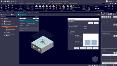
By right-clicking an ordered feature, a suppression variable can be added which takes a value of either 1 meaning it is suppressed or 0 for un-suppressed.

To access the variable created by this command, open the Variable table from the Tools tab on the Ribbon. The variable name is often found to be FeatureName_Suppress

The downstream applications of this feature are many. You can link this variable with an Excel sheet simply by copy-pasting to set up a simple part configurator. I will share a video for setting up such a configurator in an upcoming article.
Meanwhile, here’s an article that shows how to link Excel cells with the variable table in Solid Edge.
GoTo and Parents-Children
If you are new to Solid Edge, it would be of interest to know the GoTo and Show Parents & Children commands. The GoTo option rolls back the model to the right-clicked feature so you can insert a feature at that point in time in case you had forgotten or simply view the model state with just those features.
The Parents & Children command highlights the features on which the right-clicked feature is dependent on meaning any change to the parent is going to affect the selected feature. The children are those features which could be affected in one way or other when the right-clicked feature is modified.

Feature Groups
Grouping ordered features have the benefit of managing them together. For instance, when you add a suppression variable for a Feature group, only one variable is created for all the included features which can be controlled using a single variable. This can save a lot of hassle when managing the suppression state of a bunch of features to arrive at a model configuration.

 Note: To view the suppression variables in the variable table, simply right-click anywhere in the graphics area other than the model and choose Variables… from the context menu that appears.
Synchronous Modeling
If you hesitate to jump straight into Synchronous modeling for some reasons, Solid Edge provides a middle way. You can right-click an ordered feature and choose to Move to Synchronous, the only rule being that features preceding the right-clicked one will also be migrated.

Synchronous is thus the best of both worlds and here’s a quick list of some of the benefits:
- You can continue adding ordered features on top of any synchronous features.
- Ordered features can reference faces and edges of synchronous features.
- You can edit ordered features using regular history-based methods.
- You can modify synchronous features using the synchronous techniques like the Steering Wheel.
Synchronous Right-click Settings
- In the Synchronous mode, sketches form regions which can be pushed pulled to create features like protrusions and cutouts without the need for invoking these commands explicitly. To prevent sketches forming regions automatically, right-click a sketch and set this option.
- Also, when creating features from sketches, the dimensions of the feature should migrate to the features automatically and aid in feature manipulation later. If you don’t see this happening, right-click the sketch and select Migrate Geometry and Dimensions.

User-Defined Sets
This is another feature available exclusively from the right-click menu in the PathFinder.
Often you may have noticed that checking PMI On will make all dimensions in the model visible increasing clutter.
Right-click a bunch of related dimensions and create user-defined sets of them. Now it is possible to selectively display dimensions in different portions of the model making edits easier and hassle-free.

Some other object types that can be made into user-defined sets are:
- Faces
- Features
- Complete sketches
- User-defined reference planes
- User-defined coordinate systems
There is no end to the number of features and areas of the Solid Edge UI where right-clicking will pop-up surprises. Who knows what you might end up adding to the PathFinder.
One such example is the Part copy command which adds a feature to the PathFinder right-clicking which gives some interesting options to update the link, open the linked model and even drop the parents.
Hope you are enjoying the series.
Taking hints from these articles, explore more and share them in the comments.
So right-click right away!
And also don’t forget to check out these other articles in the series:
Right-Click Options – Part Environment
Right-Click Options – Draft Environment
Right-Click Options – Assembly Environment
Right-Click Options – Solid Edge UI
Right-Click Options – OS Related
Tushar Suradkar
Solid Edge User Group on Facebook:

Comments
Leave a Reply
You must be logged in to post a comment.
Wow, I wish I could find work appropriate words to describe my frustration with this “feature”, but I can’t. How about just one click to suppress a feature as opposed to whatever this is.
Wow. Really? Wow.