Reverse Engineering Tutorial Part 1 – Get Your Feet Wet

A few weeks back an article on reverse engineering appeared in the community blog and got a great response, followed by another inquiry on the forum about a beginner tutorial on this topic.
This tutorial shows just one of the many ways in which scanned data in the form of a mesh can be converted into a Solid Edge model.
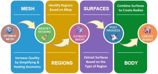
The reverse engineering process can typically be accomplished in the following 5 steps:
-
- Import and optimize the mesh.
-
- Identify regions based on various boundary representation type.
-
- Extract surfaces based on the identified regions.
-
- Post-process the surfaces to make them fit for body creation.
-
- Combine the surfaces to create the final Solid Edge model.
This process is illustrated in the following infographic with the Solid Edge commands involved at each step.
 Import and Optimize the Mesh
-
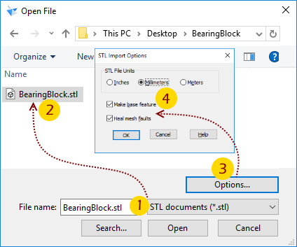
- Download the BearingBlock.STL file.
-
- In Solid Edge press Ctrl+O.
-
- In the File Open dialog, select STL documents from the drop-down list at the bottom.
-
- Select the downloaded STL file.
-
- Click the Options… button.
-
- Check ON the boxes for the base feature and heal mesh.
-
- Select the ISO metric part template.
-
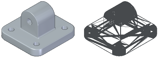
- When the model loads, change the view style to wireframe.
-
- Note there are no regular faces.
 A Quick Primer
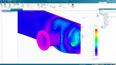
A mesh body is made up of triangular polygons, called facets. Each facet has three vertices and three edges.
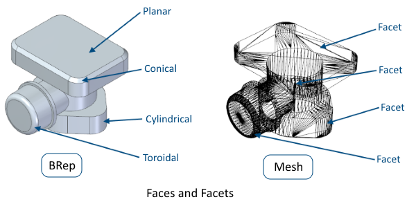
The facets of a mesh can be collected into faces. These faces are similar to the faces in Solid Edge BREP bodies, except that mesh faces do not have a geometric description.
For example, two or more facets of a mesh can make up a rectangle, but that face is defined simply as a collection of facets, not as a rectangle with a height and width.
-
- Back to the mesh model open in Solid Edge
-
- Note the blue i symbol in the Pathfinder and read its tooltip.
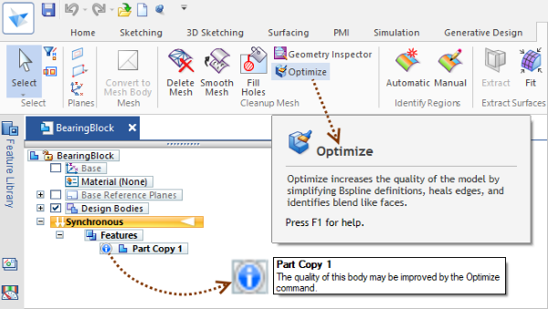
The Optimize command mentioned can be found on the ribbon bar – Reverse Engineering tab.
-
- Start the Optimize command, which selects the model automatically.
-
- Right-click to finish.
-
- Close the report dialog if it appears.
This finishes the first of five steps in the reverse engineering process in which you imported the mesh model by opting to create a base feature – a part copy and to heal any faults in the mesh. After this, you optimized the imported model, though I am not sure how relevant this command is for an imported mesh.
Later in this tutorial, you will see an example of using the Optimize command to simplify curves and surfaces.
 Identify Regions
This can be done either manually or automatically. The Manual command is shown in the video below which also illustrates some tips about rectifying mistakes while painting facets.
It is clear from the video that Solid Edge designated colors should be used for each type of face. Here’s the full list of the color codes:
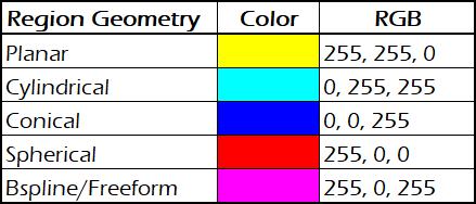
These colors are in fact used by Solid Edge internally to identify regions in the Automatic command.
Open the BearingBlock.STL (if you have already downloaded) file one more time and try out the Automatic  command which produces the results as seen below which are not quite as expected, perhaps because this is not really a scanned model, but in fact, I have saved out a Solid Edge regular model to an STL and shared for this beginner tutorial.
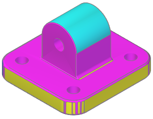
Close this file without saving and continue with the one that has regions identified manually as per the steps in the video.
This finishes the second step in the process of building a solid model from an imported mesh.
 Extract Surfaces
The steps involved are shown in this 45 seconds video:
![]() Note: Instead of the manual method using the Fit command, you can also use the Extract command which produces the same surfaces – automatically.
Note: Instead of the manual method using the Fit command, you can also use the Extract command which produces the same surfaces – automatically.
In both cases, lots of surfaces are generated and in some other cases additionally, spherical, conical and BSpline surfaces are generated too. If you want to toggle the display of these surfaces based on the type, here’s a free macro that does this in a jiffy:
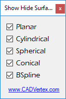
![]() Download the macro from this page.
Download the macro from this page.
This finishes the third step of the reverse engineering workflow discussed in this beginner tutorial.
 Post-Processing
The extracted surfaces leave a large gap between them at several places as you would have noticed and these need to be closed by extending them.
Another important operation is adding tangent ‘face’ relationship at a couple of places where the top cylindrical face connects the planar faces, since they have all been created from different mesh facets, independent of each other, and may not be actually tangent.
The video below shows all the steps involved.
![]() Note: If you want to skip this laborious process, download this Solid Edge 2019 part file with the surfaces extended.
Note: If you want to skip this laborious process, download this Solid Edge 2019 part file with the surfaces extended.
![]() Tip: You can still use the part to cross-check the edges which need to be extended by hovering the mouse cursor over each Extend feature in the Pathfinder.
Tip: You can still use the part to cross-check the edges which need to be extended by hovering the mouse cursor over each Extend feature in the Pathfinder.
This completes the fourth step in the process.
 Combine
The Intersect method is used to combine the surfaces to create several distinct bodies which can be further combined automatically by setting an option in the same command as seen in the short video below:
The ‘Create design bodies’ option is perhaps new to Solid Edge 2019, but I am not sure about this.
This finishes the core reverse engineering workflow.
The next part of this tutorial shows:
-
- Several techniques to extract the holes and the rounds from the mesh model.
-
- Best practices for reverse engineering with Solid Edge.
-
- How to perform modeling operations directly on the mesh model.
Tushar Suradkar
Comments
Leave a Reply
You must be logged in to post a comment.

I can’t access the file. The link sends me to the community homepage.
Hello Ajay,
Not just that.
Your message missed me too.
The blog was migrated to this new platform from an older format.
The file appears to be lost in this transition.
I suggest sending a message to community administrator with a request:
https://community.sw.siemens.com/s/profile/0054O000006VCOtQAO
None of the links seem to work to download files, watch the video, etc.
Hello Tushar,
it is great to have a tutorial for the Reverse Engineering module. I really would like to do some tutorials in RE, but as the 2 colleagues wrote before, the links do not want to work. I guess the page does not exist anymore, because it has been migrated into a new one. Could you please be so kind and update the links?
Thanks a lot,
Balint
Hi Balint,
Sorry to have missed you message as I never got a notification from the blog platform.
I found this message accidentally.
I too do not have the backup files used here.
I suggest contacting the Siemens admin and request the files:
https://community.sw.siemens.com/s/profile/0054O000006VCOtQAO
Tushar . Suradkar @ gmail . com