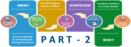
Reverse Engineering Tutorial in Solid Edge Part 2 – Deep Dive

Step 6 – Extracting Treatment Feature Data
The intention of the reverse engineering process is to extract a high-level overall form of the object and it is not recommended to extract treatment features like holes, rounds, chamfers, etc.
The following video shows various techniques to extract measurements or sizes of the treatment features present in the mesh model for use in Solid Edge:
Step 7 – Reverse Engineering Best Practices
The video below shows with examples a couple of best practices to be followed in the reverse engineering process in Solid Edge:
Step 8 – Mesh Repair and Direct Mesh Modeling
Finally, the following video shows how you can perform modeling operations directly on a mesh model without having to extract surfaces or create a design body first.
Also, the video shows how to delete a portion of the imported mesh body and heal mesh regions manually by filling in holes and gaps.
Tushar Suradkar


Comments