Out of the Box Tools for Solid Edge
If you don’t know already, Solid Edge ships with over 2 dozen programs and utilities which can be readily used in various scenarios in daily work. Moreover, the full source code is made available so they can be easily modified and adapted to your specific needs.
The intention of this article is to make you aware and introduce each program in brief, what it does, how to use and requirements to run the programs if any.
How to Access the Programs
The most reliable way to locate the program folder is to right-click on the shortcut that you use for starting Solid Edge.
If the Solid Edge icon is on the taskbar, follow the steps shown below:

If the Solid Edge shortcut is placed on the desktop or you prefer the Start Menu every time to launch SE, then the Properties item can be accessed directly by right-clicking the icon.

This opens the Properties dialog.
Click the Open File Location button.

This starts the Windows Explorer with the Program folder opened.
Move a level up to the parent folder and open the Custom folder.

Assembly Relationship Doctor
Location: CustomAsmRelDoctorbinAsmRelDoctor.exe
Requirements: Solid Edge Should be running with an assembly open.
The program may take some time to finish execution depending on the size of the assembly since it examines the assembly relationships and the ones causing problems will be suppressed. After this, the assembly should solve successfully.
The result of the diagnosis are written to a text file in the same folder as the assembly and the file name will be the same as the assembly, with a.txt extension. The text file lists the troubled relationship and its parts.
Batch Processor
Location: CustomBatchBinBatch.exe
Requirements: Solid Edge Should be running and all files are closed
This is the most popular program among users which can be used for three types of batch processing:
-
- Printing a bunch of Draft files from a folder.
-
- Converting a set of files into Solid Edge. For example, converting a set of DXF files into Solid Edge Draft.
-
- Converting Solid Edge files into other supported formats.

Until around ST7 or ST8, there was no option to specify an output folder. So if you are still using a pre-ST9 version, download a modified version of the batch program that has the button from this discussion on the community forum.
The program displays a message ‘Finished processing’ in the status bar of the program dialog when all files are converted.
Bearing
Location: CustomBearing – But no program to run.
Requirements: Solid Edge and MS Excel are installed.
The Bearing sample demonstrates how a user can link cells in a Microsoft Excel spreadsheet to variables in a Solid Edge part.

How to use:
Open the Excel file Bearing.xls
Open the file Bearing.par in Solid Edge.
Click on the Update button.
Solid Edge will update the part file to reflect the new values.
Note the Paste Link rule and the format of the formula in the image above.
 Tip: Open the Variable table in Solid Edge by right-clicking in an empty space in the graphics area.
You too can create such parametric parts with basic Copy-Pasting skills and Solid Edge takes care of the rest.
Read a step-by-step tutorial on how to set up such Excel-Solid Edge part linking. See the section ‘Putting it All Together’.
Another advanced tutorial about Excel and Solid Edge linking can be read here.
Assembly Structure
Location: CustomDesignManagerbinAsmStruct.exe
Requirements: Solid Edge need not be running.

This program uses the Design Manager, formerly called the Revision Manager in the background to display the assembly structure. Useful for quickly viewing the components of an assembly without having to launch Solid Edge. The numbers on the left are the assembly depth for each component in the hierarchy.
Draft Spell Checker
Location: CustomDraft Spell Checkerbin Office 2013Draft Spell Checker.exe
Requirements:
-
- MS Word is installed.
- Solid Edge should be running with a Draft document open.
Solid Edge Draft doesn’t come with a spell checker built-in but this program does the job by synergizing the two programs. It borrows the dictionaries and spelling checker capability of MS Word and performs a spell check on the text in Solid Edge Draft sheets.
Dynamic Attributes
Location: CustomDynAttribbinDynAttrib.exe
Requirements: Solid Edge should be running with any type of document open and an object pre-selected.
An attribute is nothing more than a piece of information like text or numbers that you want to attach to an object in Solid Edge and retrieve it later without cluttering the screen by use of a Textbox or a Callout.
In simple terms, this program attaches a note to any selected object like a Hole or a Drawing View, a Line or an Assembly Component and retrieves it later using the same UI.

Another practical application of this facility is the Revision Cloud macro.
Watch a video of the macro which is also available on the Solid Edge Apps Market Place.

To know what goes under the hood, understand how to store and retrieve such hidden information and write similar apps, read an in-depth developer tutorial here.
Hole Database Converter
Somewhere during ST6 or ST8, the format of the holes.txt changed to Excel.
This utility converts the Holes.txt files to the .xlsx format
Location:CustomHoleDatabaseConverterbinHole Database Converter.exe
Requirements: Solid Edge need not be running
To use,
-
- Run the Hole Database Converter.exe
- Pick the files to be converted using the Add button.
- specify a directory to save the .xlsx files using the Browse button.
- Click Convert.
After this make sure the holes database path matches that specified in the Solid Edge Options dialog:

Preview 3D Models
Location: CustomImportSEx64ReleaseImportSE.exe
Requirements: Solid Edge need not be installed.
This program lets you select any Solid Edge 3D file and preview it in a resizable window even when Solid Edge is not installed on the computer.
Another advantage of this over the Windows Explorer preview is you can zoom, pan and rotate the model using the mouse as shown below:

Polygon
Location: CustomnSidePolygonbinnSidePolygon.exe
Requirements:
A Draft document should be open, or
The sketcher mode is active in a Part/Assembly/Sheetmetal document.
This program existed from the earliest versions of Solid Edge when the Polygon by Center command was not yet added.
 When I tried this program recently, the message at the bottom of the dialog said Getting Solid Edge for a long time, but I went ahead and clicked in a Draft sheet and it created a pentagon as shown above.
Open Save
Location: CustomOpenSavebinOpenSave.exe
Requirements: Solid Edge should be running and all files are closed.
This is another batch processor which opens Solid Edge files and saves them in the current version.
If you are on ST4 or later, the program also lets you update the 3D Face Styles.

The program updates drawing views in Draft files and I have shared a modified version of the program that also updates BoMs.
Download the modified program from this message in the community forum
Batch Generative Design
Location: CustomReGenReGenbinReGen.exe
Requirements: Solid Edge should be running.
The ReGen tool provides a means for generating results for all Generative Design studies in any number of part files unattended. This is useful if you have multiple studies that need results generated. Since generating results can be a lengthy process, it is often not practical to manually generate the results interactively.
Assembly Relationship Browser
Location: CustomSEAssemblyRelationshipBrowserbinSEAssemblyRelationshipBrowser.exe
Requirements: Solid Edge should be running with an assembly open.

The Assembly Relationship Browser displays all assembly relationships for the currently open assembly document. This tool provides a means for filtering which types of assembly relationships are displayed in the list as well filtering which assembly relationships are displayed based on relationship status.
Filtering the displayed relationships based on status can help troubleshoot which relationships are causing problems in the assembly i.e. causing occurrences to display with a lightning bolt in Pathfinder.
Solid Edge Library
Location: CustomSELibrarybinSELibrary.exe
Requirements: Solid Edge should be running with an Assembly file open

The program first asks to locate the required SE-Library.dat file which can be found in the folder CustomSELibrary
Next, choose the desired component and size from the dialog where different parts are listed on each tab and the variations listed in the list box below.
Toggle between the drawing and the part by clicking the Show Part or Drawing button.
The component can be added to the active assembly using the Add button. If the selected part is not found, the library manager will create the part using a base part as a template, and modify the part dimensions per the selected size. Once created the part will be appropriately named and stored in the installation path specified above.
Note: The name is a combination of the part type (listed on the tab) and the contents of the first column.
Solid Edge Movie Recorder
Location:
CustomSolidEdgeMovieRecorderSolidEdgeMovieRecorderbin SolidEdgeMovieRecorder.exe
Requirements: Solid Edge should be running with an Assembly open.

This program records the assembly movements and is similar to the built-in screen recorder but with finer control and options for movie format, codec, resolution, frame rate, bit rate, and movie information.

 There are several more programs like the Custom Sensor, GandT for sheetmetal, Number Generator, Change Locale, Link Checker, Mouse Events, Pipe Utility for which the details can be read in the respect Readme files.
Besides, these the Solid Edge Start Menu group lists several data migration programs and above all the Settings and Preferences Wizard
This tool was introduced in ST9 and allows you to capture, deploy, or restore factory settings.

Once you capture the settings, choose a location for the settings file to be saved. The tool also captures your template files and some other files from the originator’s Preferences folder like those for holes, sheet metal gage table, pipe threads, materials, wire harness preferences, and lots of other stuff that is great to have standardized between users.
Once you’ve got the settings and preferences file created and saved, you need to point individual users to the file which should preferably be kept in a network location. You can do this in Solid Edge Options > User Profile > Settings and Preferences.
Cleanup Tool
Further, if you have the Solid Edge installation DVD, the Cleanup tool in the folder DVDSolid EdgeSptToolsSECleanup can be used for removing registry entries.
Caution: Do not run the clean-up tool if you have Solid Edge installed and running. This tool is only to be used in the event Solid Edge removed via Add/Remove Programs failed to successfully remove the product.
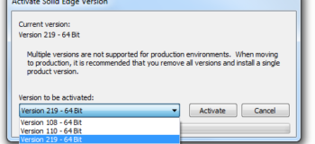
Another Set Active Version tool found in the folder DVDSolid EdgeSptToolsSESetActiveVersion is useful for switching between multiple installed versions of Solid Edge on the same computer so that only one is the active version at a given time.
This tool is however not supported in a production environment but generally used by beta users who must continue to use their existing version and test an upcoming release of Solid Edge.
Tushar Suradkar