New in Solid Edge 2024: AI and productivity enhancements

This year, we’re taking a deep dive into everything that’s new in the Solid Edge 2024 release in a series of blog posts focused on the most noteworthy new features and enhancements. In this post, we’ll cover productivity enhancements in Solid Edge 2024.
The new automated features in Solid Edge 2024 and the use of Artificial Intelligence to speed up common tasks is going to be very beneficial for our team. – Uchiyama Takahiro, EagleBurgmann
Get better results, faster, with Artificial Intelligence (AI) in Solid Edge. When replacing parts in an assembly, new AI assembly relationships intelligently predict and offer valid alternatives. An AI-powered user interface learns your behavior to show you relevant commands in the right context. Synchronous technology’s intelligent modeling capabilities recognize and maintain design intent in real time, even on models coming from other systems. And generative design capabilities add machine intelligence to concept design, automatically computing geometric solutions from defined constraints.
Artificial Intelligence (AI) assembly relationships
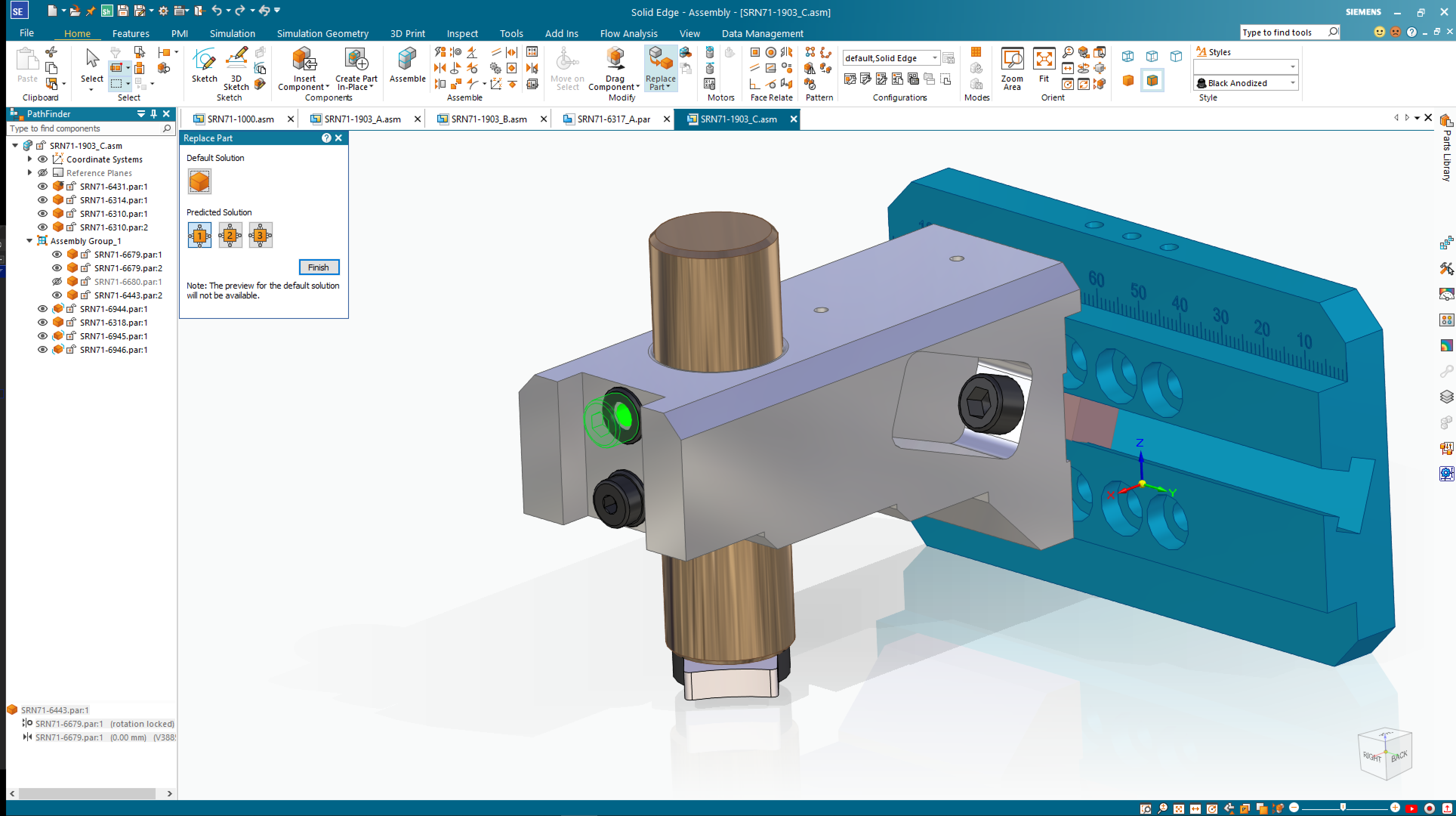
Leverage the power of Artificial Intelligence (AI) to save time when replacing parts in an assembly. With the improved “Replace Part” command, Solid Edge can now intelligently suggest assembly relationships and predict valid alternative solutions. The predicted solutions are graphically previewed in the design environment and can be easily selected in a pop-up dialogue.
The AI-enhanced “Replace Part” functionality also supports the creation of assembly relationships when utilizing parts from the Standard Parts and 3DfindIT parts libraries.
Handed parts with full feature tree
Many designs require symmetrically opposite parts or handed parts. These parts are identical, mirrored copies of one another. A new streamlined workflow makes it easier and faster to create these left- /right-handed parts that can remain associative to the original part if needed.
Handed parts can be created using one of two new workflows: the new “Remove Original” option to within “Mirror Copy Part” command, or the new “Save as Mirrored Part” command. Each is much simpler than the previous workflows required to create such a part. The new, handed parts created with these workflows can remain associative to the original part, if desired, by using the “Link to Original” option.
Handed parts can also be created complete with the features used to create and build them, making it easy to parametrically edit the new part. The mirrored part commands is supported in both the Ordered and Synchronous environments.
User-driven productivity enhancements

Family of Parts: The customization options within Family of Parts continue to expand. The following options are now available and supported for each individual member: material, file properties, etches, flat patterns, simplified bodies, multi-bodies, coordinate systems, reference planes and sketches.
Part Copy: The ability to easily match coordinate systems when copying a part has been added. Users can choose the coordinate systems for a copied part within the “Part Copy Parameters” dialog. Setting the two coordinate systems to same will result in matching the origin and axes orientation between the two coordinate systems.
Polygon/Lasso Selection: Users can now have greater control of selecting objects when using the “Polygon/Lasso Selection” fence option. A lasso selection allows the user to select objects with a freeform drawn fence, while a polygon allows users to select the multiple vertices of a polygon fence. This enhancement is an addition to the normal “Rectangle Fence” option and is available in the 2D and 3D environments.
Automatic Tube Trim: An often-requested enhancement, the new “Trim Tubes” command automatically trims and cuts holes in intersecting tubes in the assembly environment. Users can define the primary and secondary tubes and the “Trim Tubes” command intelligently cuts holes in the primary tubes to the outside diameter of the secondary tubes and trims the secondary tubes to the inside diameter of the primary tubes. An additional feature of the “Tube Trim” command is that end-connected tubes can also be automatically mitered.
Sheet Metal Bend centerlines: Bend centerlines can now be displayed in the Flat Pattern environment in Part/Sheet Metal. The centerlines are color coded, identifying the direction of the bend, leading to better understanding, and avoiding confusion when working with flat patterns.
Reorder assembly features: Users now have the option to reorder features to manipulate resulting geometry, which was previously only available in the part modeling environment, has been extended to the assembly modeling. It is one of the most requested improvements from customers.
Enhanced Search: As complexity and assembly sizes grow, it can be difficult to locate parts within an assembly. New search enhancements make finding the right part easier. Users can input simple search terms and/or wildcards to search for part names. The new search enhancements work with the Parts, Feature, Block and Symbol libraries.
Remove disjoint regions: Unwanted regions left as the result of a subtract operation, or disjoint regions, can be easily removed with a new enhancement to the “Subtract” command. An optional “Select Region Step” has been added to the workflow where the disjoint regions can be intelligently identified and automatically removed.
Variable table filters: Access to filters in variable tables has been improved. Users can now access the filters more quickly and easily, saving time, reducing mouse clicks, and enhancing usability of the variable tables.
Resolve conflicting relationships: When placing parts, conflicting relationships can now be automatically identified, giving the user the ability to resolve the conflicts. A popup dialog displays the conflicting relationships. The user can then select the relation from the table to see the conflict graphical highlighted in the model view. Conflicts can then be suppressed, and new relations can be defined, saving time during part placement
UI improvements
Solid Edge 2024 also introduces new features in the user interface designed to enhance productivity while bringing the latest news, promotions and in-app free trials directly to the user.
A one-stop shop for news, promotions and access to free trials, the new Discovery Center helps users get the most out of their Solid Edge experience. Content is displayed in a queue and is personalized for each user. The queue provides a preview of the information, and when selected a detail pane to the right of the queue will display additional information. Content featured in Discovery Center promotes product news, in-app trials, limited time offers and more. The details panes provide users with images, videos, learn more links, and the ability to try or buy add-on products.
The 30-day, in-app trials give users the ability to try eight add-on products, without the need for additional downloads and installations. Trials are offered for the following add-on products: XpresRoute, Generative Design Pro, Electrical Routing, Point Cloud Visualization, Advanced PMI, and Simulation Standard and Advanced. Content can be filtered and bookmarked giving users‘ access to the information in which they are most interested.
With recent document preview users have a new, dynamic file open process to quickly and cleanly access most recently used files. A single mouse click in the “Quick Access Toolbar” will graphically display the most recently used files with previews in a ribbon. Users can select the file to be opened by releasing the mouse button. The file preview ribbon can be displayed vertically or horizontally based on user preferences.
Physical thread clearance for 3D-printed parts
Many issues can arise for 3D-printed parts with physical threads, leading to unusable designs and subsequent prints. Threads without appropriate clearance often cannot be assembled as intended once printed.
Two new options have been added to the “Thread” command to help users define physical thread clearance when designing parts to be 3D printed. These new options allow users to enter additional clearance values by percentage or by an absolute value. The thread’s internal diameter will be increased, or the external diameter will be reduced by the percentage of the nominal diameter or absolute value. Clearance values vary by the material, process, and 3D printer.
All of these new features and enhancements in Solid Edge 2024, along with many more, were announced during our live premiere on October 11, 2023 @ 10:00 EDT.
To learn more about what’s new in the Solid Edge 2024 release, click here
Join the conversation
There are a lot of ways to hear what others are saying about the upcoming release and to connect with other Solid Edge enthusiasts online.
Here are a few ways to join the conversation right now:
- Keep up with #SolidEdge2024 on Facebook, YouTube, Twitter, and LinkedIn.
- Join our vibrant online Solid Edge Community to connect and interact with other Solid Edge users.


