Multi-Body Modeling Part 3: How to Make Multiple Bodies
Making multiple bodies in a single part is easy. Here are a few methods for doing it:
Disjoint Solids
When you create solid regions that don’t touch one another, these are called regions. Technically, you can have multiple regions within a single body. So sketch a rectangle, extrude to a solid. Sketch another rectangle and extrude another solid in the same part that doesn’t touch the first solid, and you have 2 regions, one body. I’m kind of hammering on this because it’s confusing to me, having worked with a different system for too many years. This concept of “disjoint solids” is why you have to be more careful about how you use the term “multi-body” in Solid Edge.

If you want to download the part used to make this image, it is attached to this post with the name mbm1.par. It’s very simple, but you should be able to see what was done pretty easily, and play around with it without fear of breaking anything important.
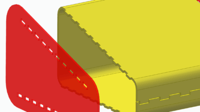
 In the image above, the cursor is over Design Body 1 in the Pathfinder, so the two regions that comprise that body are highlighted orange. By default those would be transparent gray because they are inactive. Design Body 2 is a single region, and is the active body. I created the Design Body 2 entry in the Pathfinder by using the Add Body tool shown to the right.
So extruding disjoint sketches just makes solid regions until you use the Add Body command. This is the first and easiest way to make multiple regions/bodies in Solid Edge.
 Insert Part Copy
The next tool to talk about is the Insert Part Copy command. This enables you to insert one part into another part, where all that shows up in the second part is a single feature. It’s not clear to me why this command shows up on the Clipboard group of the Home tab, but that’s where you’ll find it. The interface is customizable, so if that really offends you for some reason, you could put it somewhere else that makes more sense to you.
When you use this feature in Synchronous, it is not associative. The first time you use it, you’ll get a message like this:

I’ve seen a lot of people who ignore messages like this, or assume that no message the software sends out is useful. Don’t be one of those people. At least read the message before judging its usefulness. This one is pretty  clear. So if you make a change to the original model, the Insert Part Copy will not update. Sometimes that’s exactly what you want, and sometimes it isn’t . If you want a feature that will update with changes to the original file, switch to Ordered mode, and use the Insert Part Copy that way.
The Part Copy Parameters dialog helps you insert the existing part into the new part. The existing part, which I call the “parent part”, can be multi-body or multi-region. For example, I used the mbm1.par part used in the example above as a parent part to put into a new part using the Insert Part Copy.
To use this tool, just create a new part or open an existing part. This part I call the “child part”. Then click on the Insert Part Copy from the Home tab, Clipboard group. Acknowledge the message discussed above if you are in Synchronous mode.
Then the dialog to the right appears. This gives you a lot of options.
The “Family of Parts member” drop down allows you to select one specific member from the parent part’s family of parts. This could be a specific size or a version with or without certain features.
“Copy as Design body” inserts the parent part body(ies) as design bodies.
“Merge Solid bodies” will merge the bodies from the parent part with bodies of the child part.
“Mirror body” of course gives you an opposite-handed part from the original, and you can even use the Scale tool to do uniform or non-uniform scaling.
“Flatten” is for sheet metal bodies.
Moving bodies with Synchronous is pretty easy. Just select the body in the Pathfinder, and use the Steering Wheel to move the body to a new location. Much easier than other software I’ve used.
 Cutting a Body
I used the mbm1.par to create this cut. I first activated Design Body 1, then sketched a rectangle on it, and extruded the section of the the rectangle over the block to make the through cut. This does not create another body, it creates a region. Again, if you get this concept of “regions”, I’m sorry for emphasizing it, I’m doing it primarily because I’m still having a hard time with it. From here, it’s unclear to me how to separate the regions into bodies if you have the need to do that.
Split
Split is one of the more useful MBM tools, in my opinion. Split will allow you to split a solid into multiple bodies with a plane, another solid, or a surface. It’s very handy. One shortcoming of the tool is that it seems to only work on a single body at a time (you cannot split multiple bodies, although again, you can split multiple regions within a single body).
Divide
I’ve heard of this “divide” feature. It looks like it was hidden in ST5 and possibly removed in ST6. I can’t find it in the Customize interface. It appears to be superceded by the Multi-body Publish feature. Maybe someone can correct/confirm here. It’s hard not being the expert. In any case, Divide appears to be a legacy feature.
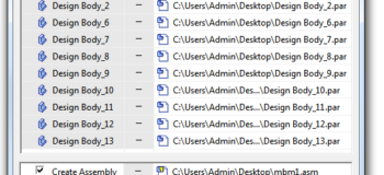
Multi-body Publish
Multi-body Publish is kind of the end of the MBM process. This feature allows you to push each body out to individual part files. It will also bring all of these separate parts back together into an assembly. This is great. It’s a cool tool, does what it needs to do, is easy to use, and self-explanatory.