Products
Making a Block Suitable for Schematics
Solid Edge installs with a lot of blocks that you can use for annotations and schematics, but the need may come up where you need something that isn’t supplied. You have to make your own. It isn’t hard, but there are some additional items you can do to make the annotation of your schematics somewhat easier.
- Start with a draft document. This seems obvious, but I just thought it needed to be said.
- Switch to the Sketching tab and draw your block.
- Set up your Library view as described in the previous blog post on Schematics.
 Select the library document you want to add your new block to, or save a new draft document with an appropriate name.
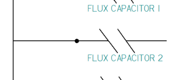
- On the Blocks group, click the drop down, and select Block Label from the list. This creates a label for the block that can be different for each occurrence of the block. For example, you might have two occurrences of this block we are creating on a drawing. One might be called Flux Capacitor 1 and the other might be Flux Capacitor 2. The options to the right of the Name and Value fields will help you get this set to behave the way you want, and the options below will help you get it set to look the way you want.

- At this point you may want to check the scale of the items. Pull in a sample block that the new block will be used with. From the Draw group, select the drop down list for Mirror, and click on Scale. Then drag a window to selectall the sketch elements that you want to scale, and click-and-drag or enter a number in the CommandBar to resize the items for the new block.
- Now

click the Block icon (far right of Sketching tab), and drag a window to select all the sketch elements and the text. Right click to accept selection. - Following the active icons on the CommandBar and the prompts in the PromptBar, continue by selecting an origin for the block. This will be the red point that is attached to the cursor when you place the block.

 After you assign the origin, the CommandBar interface will change slightly to include the name and some other settings. The name will be used in the Library window to identify this block to make it easier to identify and use later. This name is different from the Block Label name (which I called “Annotation” in step 5 above.)
- The Place Occurrence option when active will replace the initial lines and text on the sheet with an occurrence of the actual block. This is on by default.

- Scale Dimensions and Annotations enables any dimensions and annotations shown with the block to be scaled up along with the geometry when the block is resized.
- Clicking the final Accept brings up the Block Properties dialog, which enables you to review and edit any of the items you have entered. When you click OK on this box, the Block Label “ANNOTATION” on the block will change to the value “FLUX CAPACITOR”.
- If you drag a second occurrence of the block on the drawing, the Block Properties dialog will pop up again, giving you the option to add designators such as FLUX CAPACITOR 2. In this way a schematic with multiple of the same blocks still allows you to identify each block occurrence separately.


Comments