Design Optimization in Solid Edge
I guess you can say this is an “oldie but goodie” in Solid Edge Simulation. Well not that old, introduced in ST6, we bring to you the advantages of design optimization. Do you need to optimize your design for weight, stiffness, stress, etc? Or, how does increasing the load on a design affect the results? If so here are some examples that will help you understand what is available. Recognize Solid Edge Simulation is available as part of our Premium package but can be purchased as an addition to Classic or Foundation.
Inputs to Design Optimization
The basic inputs to a design optimization study include:
- Reference to an existing study
- Design Objective
- Design Limits
- Design Variables
- Control Parameters
Existing Study
In order to run a design optimization study you must have in the document a completed study which has already been run. This gives the optimization process a starting point with results from which to optimize.
Design Objective
This is the foundation of the objective you are trying to achieve. Available for use as the objective are physical properties (Mass, Volume, Surface Area) or any Simulation Study results from the existing study. Most typical applications for the objective is to minimize mass or maximize stiffness. Note you can have only one objective for each optimization study.
Design Limits
Design Limit inputs are the same as the design objective, Physical properties and Study results. Design limits control the solution based on the limits defined in the study. For example, quite common is to set the objective to minimize mass with the limit that maximum stress cannot exceed allowable stress (ie, Yield Stress/Factor of Safety(FOS)). Note you can specify/add as many design limits as you want in the optimization process.
Design Variables
Design Variables are the parametric variables in the model you want to adjust to meet the objective based on the limits applied. Note you can have as many design variables added to the optimization process as you would like.
Control Parameters
I won’t go into the details here but there are a number of control and convergence parameters that can be set to control the precision of the optimization. I typically take the defaults with one exception which will be noted in Case Study 1.
Case 1 – Idler Pulley
This is an idler pulley (containing an existing study) with the following conditions/inputs:
- Objective – Minimize Mass (currently 7.281 lbm)
- Limit – Maximum Von Mises <= 1333 – Allowable Stress (YS/FOS)
- Variables – Angle and Height (note limited range in the variable Table)
- Torque Load and Fixed Constraint
- Current Maximum Von Mises Stress – 932.4 psi
So the setup is to adjust the angle and height of the cutout (using the ranges set in the variable table) which will minimize mass but make sure maximum stress is less than allowable stress. Original Design with Boundary Conditions
 Initial Results
Setting up and optimizing the pulley for minimum mass while maintaing allowable stress produces the following results.


You can see from the XLS the optimized mass was reduced 17% to 6.027 lbm in iteration 7 and the “Angle” variable was just under 90 degrees and “Height” adjusted to 3.63 in.
You can also see after iteration 7 the optimization over-shot the limit (red cells) of allowable stress but close. I should say Iteration 11 was within the limit but it shows the need to evaluate all results. This is a result of the input parameters used so you have to look at the results to find the solution desired. In fact, it would be common to look at the results (Excel XLSX) and find the solution desired (yellow column, my choice but you decide) and then edit/round the variables to something you prefer and rerun a new study (with possibly a finer mesh) to get more accurate results. Another point to note is the order for which you put the design variables in the list can affect the results as well but only slightly. In the case above I added “Angle” first and then “Height”. If I had reversed the order the results could be slightly different. Lastly, and I have not adjusted all parameters, but the one I often change from the default is the Relative Convergence (%). The default is 2.5 and I typically change it to .1% or somewhere in that range.
Case 2 – Sheet Metal Bracket
 Original Design
 MidSurface with Loads/Constraints
Here we have a sheet metal bracket (for a garage door opener) in which we would like to minimize the mass while maintaining an allowable stress below 30,400 psi. This is using a FOS of 1.2 and Yield Stress for the galvanized steel of 38,000 psi. Here we are using a single design variable of material thickness. We are starting with 8 gage steel so the initial thickness is 4.37 mm. A load of 70 lbf is applied to the top face and the four holes are fully constrained. Note since this is a sheet metal part we are using the midsurface of the model and will analyze this using surfaces/shell elements.
- Objective – Minimize Mass (Original Value 2.141 lbm)
- Design Limit – Maximum Von Mises Stress <= 30,400 psi – Original Max Stress is 10332 psi.
- Design Variable – Material Thickness – (Less than 8 gage – 4.37 mm; greater than 20 gage – .95 mm)
 Initial Results
The initial maximum stress was 10,332 psi and after optimization the maximum stress was 30,283 psi, just under our allowable stress. The optimized material thickness was 2.63 mm with a weight reduction of 39% to a final mass of 1.313 lbm. Note it would be common to find the closest gage material to this final value, set the material properties to that gage, and rerun an analysis using that gage material. In this case it would be 12 gage or 2.77 mm.
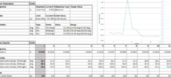
Case 3 – Roof Truss for Building


Here we have a truss structure for a building with a span of 20 feet and supports for the structure. Because it is composed of frame features we are using beam elements (1-D) for analysis. A 500 lbf load is applied to the top two frame members and the ends of the horizontal members are fixed. From the initial study we find the maximum deflection is .0314 in and maximum combined stress is 215 psi. For wood Yield Stress is 1000 psi and with a FOS of 2 we want to limit allowable stress below 500 psi.
For this optimization we want the following inputs:
- Objective – Minimize Displacement/Deflection (ie. Total translation)
- Limit – Maximum Combined Stress less than 500 psi.
- Design Variables (3 variables) Pitch Angle, Mid Angle, and Side Angles with ranges specified in the variable table.


Here you can see the maximum deflection has been reduced from .0314 in to .0147 and the maximum stress has been reduced from 215 psi to 95 psi. Also note the position for maximum deflection has moved from the original location.
Final Thoughts
As you can see, design optimization can be a great tool to understand how your design can be modified to achieve objectives you have based on limits to the results. The spreadsheet can be an invaluable tool to understand the impacts of geometric changes in the model and how it affects the integrity of the design.


