Craft Aesthetic, Unique Designs with Generative Modeling in Solid Edge
One of the biggest challenges in computer-aided design (CAD) is getting generative design, additive manufacturing and reverse engineering to work together. Solid Edge addresses this challenge by providing users with next-generation technology that brings faceted (mesh) and B-rep (feature-based) modeling together in a unified environment.
Convergent modeling, included in Solid Edge 2020, provides you with a form of hybrid modeling, allowing designers and engineers to use mesh models as if they were B-rep models. That, paired with synchronous technology, a capability that combines direct modeling with parametric design, makes Solid Edge today’s design tool of choice.
In this post, we explain the value of generative modeling capabilities and provide you with a step-by-step guide to get started with topology optimization in Solid Edge.
The Value of Generative Modeling in Solid Edge
As the design techniques like generative modeling, reverse engineering and additive manufacturing use triangulated mesh-based geometries for reference, a problem exists: Most design engineers work in CAD systems that create boundary representation (B-rep) models, which are feature-based solid models using cylinders, planes, cones, and other elements to create the design. Faceted modeling instead relies on a mesh.
Creating a great generative design from reverse engineering becomes a challenge when it’s time to modify the design using a CAD system based on B-reps. Conversely, converting 3D scans to final designs isn’t hard, but you may spend days surfacing those designs unless you’re taking advantage of b-rep CAD modeling. Generative modeling capabilities in Solid Edge solve all that by combining B-rep solids and facet models. This allows data from each to co-exist. You can also perform feature-based modeling on a mesh model. The user interaction is so seamless, you might even think you’re working on a b-rep model when you’re not.
Solid Edge eliminates the need to choose which CAD method to use. You can create organically shaped, aesthetic models that are ready for production by basically performing feature-based modeling on mesh-based parts. You can also extract surfaces from mesh data onto planar or cylindrical surfaces. With synchronous technology in Solid Edge, you can work directly on the surfaces of 3D scanned mesh geometries natively, eliminating the need for time-consuming reverse modeling.
5 Steps to Optimize Your Design Topology in Solid Edge
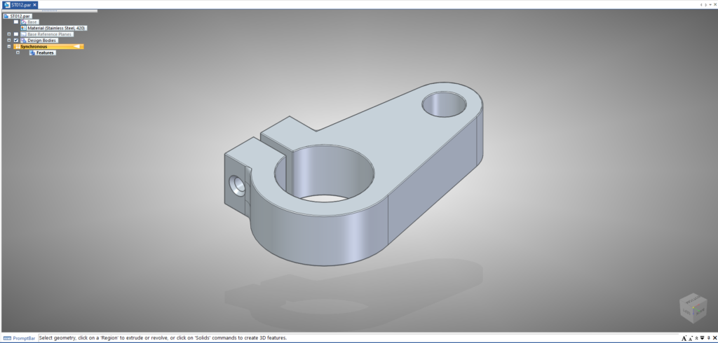
Let’s assume you want to design a shaft holder with given shaft diameters and center distance. The traditional go-to design in Solid Edge given below is perfectly fine. But, it has a major, previously unaddressed problem that the body is not topology-optimized. In other words, the design isn’t making optimal use of the material assigned to it.
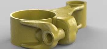
The design can be drastically improved with generative modeling in Solid Edge, effectively taking advantage of its topology optimization capabilities. Topology optimization optimizes the material layout of the design body with a given set of loads, boundary conditions and constraints, with the goal of retaining maximum performance along with optimal use of the material.
- In the generative design tab, assign a material to the base of your unoptimized design body and create a new study.
- Define the design space and preserved regions. Design space allows you to select the part that needs optimization in a multi-body design (in this case, the whole part) and preserved regions are the features of the design that don’t need to be optimized and are required as is in the final design, such as a screw drill, hole, etc.
- Apply the loads (force, pressure or torque) that the part has to bear in its operating condition.
- Define the constraints (which part of the body will be fixed or pinned) when in operation. This is the most important part of the optimization process. The region near the fixed part of the body will have to bear the maximum stresses induced. Thus, material saturation is observed around the constrained region post-optimization.
- Now go to generate. The pop-up will have two main selectors:
Quality of study determines the strength of computation that goes into the optimization. A higher quality of study needs more computing time.
Mass reduction allows you to determine how much mass needs to be cut off from the body. You must make sure that enough mass is left on the body for the computer to work with to optimize its topology.
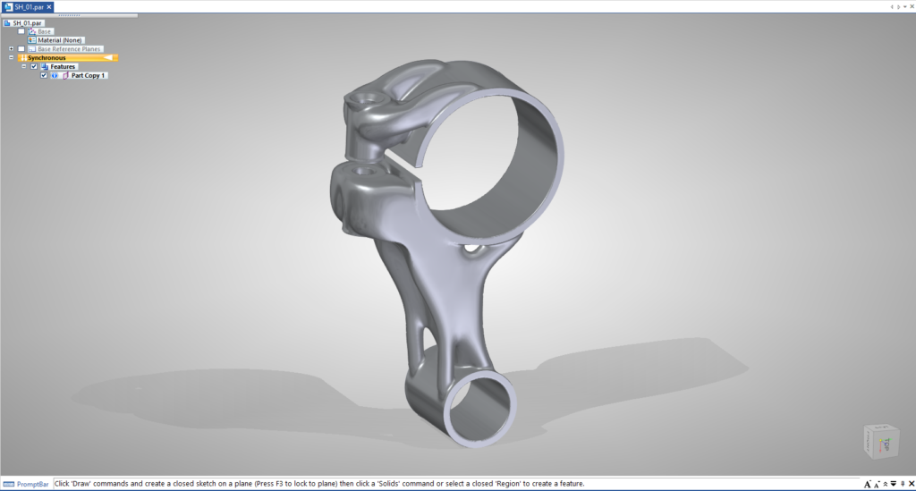
By finding the perfect balance between the mass reduction and quality of the study, aesthetic designs can be produced, resulting in reduced mass with the same structural soundness. For design engineers, practicing this method of optimization helps to find the right balance between mass reduction and quality of the study.
Try optimizing some of your own models. Simply leave a comment below or tag @mech_enthusiast and @siemenssoftware on Instagram to let us know what designs you come up with. You can also easily share your designs with other users in the Solid Edge Forum.