Building a better brewery: How modern methods improve an ancient craft

This blog post is the first in a series of three posts that focus on how Solid Edge together with Smap3D provides an excellent solution for process plant design.
 The Bavarian town of Bamburg, home of Kaspar Schulz
In 1677, the quest for the perfect pint led master coppersmith Christian Schulz to start a business in Bamberg, Germany supplying local breweries with “finely forged and hammered copper kettles.” During the next 300 years, Christian Schulz’s humble coppersmith business turned into Kaspar Schulz, a successful designer and manufacturer of brewing equipment that is installed in breweries around the world.
Alongside its vast experience of brewing processes and equipment design, innovations are critical to its success. A recent example is a new, gentle boiling process for wort. The quality of wort depends on combining different raw materials into a mash, which is agitated with a radial agitator. Because it is possible to germinate and kiln-dry in a single drum, microbreweries can brew beer to consistent quality standards and clearly establish their brand identities. These innovations are developed in collaboration between Kaspar Schulz’s brewery production engineers and equipment designers.
 Copper domes have been manufactured by Kaspar Schulz for more than 300 years
Design productivity with Solid Edge and Smap3D
In 2004, product development shifted to 3D design technology using Solid Edge® CAD software from Siemens PLM Software and Smap3D Plant Design software from CAD Partner. “Solid Edge convinced us to use these products with the integrated module for pipe routing, XpresRoute, outstanding 2D functionality and the intuitive user experience,” says Christian Montag, the team leader of design at Kaspar Schulz. “In addition, a module for sheet metal construction was integrated right from the start.” SMAP3D Plant Design software adds specialized capabilities for process equipment and piping design, plus the creation of 2D piping and instrumentation (P&ID) diagrams.
Brewing containers are designed as modular systems using variables stored in an Excel® spreadsheet. In a short time, detailed 3D CAD models are created that meet the customer’s specific needs. All the sheet metal parts are defined and developed within the Solid Edge Sheet Metal environment. A material table contains the parameters for the copper or high-grade steel materials used to manufacture the brewing equipment. Using these predefined values, the module is used to calculate all the necessary design information for sheet metal manufacturing, from cutting material to size (where the profile data is sent in DXF format to plasma cutting equipment) to bending and forming.
The designers work together on custom projects using architectural plans of the client’s premises. These plans are typically provided in DXF or DWG formats that are easily opened in Solid Edge. “Data exchange with the architects, import as well as export, works very well,” says Montag. “We usually request third party data about parts from suppliers in the STEP file format, and we’ve never had problems processing that data.” A complete 3D model of the entire plant emerges from the original 2D layout, and in the case of a large brewery, there can be as many as 10,000 components in about 600 subassemblies. “Steadily increasing module sizes poses a challenge to performance,” says Montag. “But the desired areas can be processed quickly by hiding and showing different areas with the help of different display options.”
 A complete brewery design modeled by Kaspar Shulz using Solid Edge and Smap3D
Speeding up piping design and routing
Collision detection and checks for accessibility are performed quickly. For microbreweries, achieving a tidy, elegant design and a clean, ergonomic operating environment are a top priority. The design is influenced by the pipework routing and the location of fittings and instruments. In the past, 2D schematic drawings of the pipe routing were given to manufacturing; now these design data are available in 3D. “With the 3D pipe routing with Solid Edge XpresRoute, we have made an important stride forward,” says Montag. By defining just two points within the 3D modules, the system can automatically propose collision-free paths. An important objective is to avoid welded connections because every weld seam is a potential hygienic “failure point,” and the piping data is saved in the IGES format. It is then sent to bending machines for accurate manufacturing.
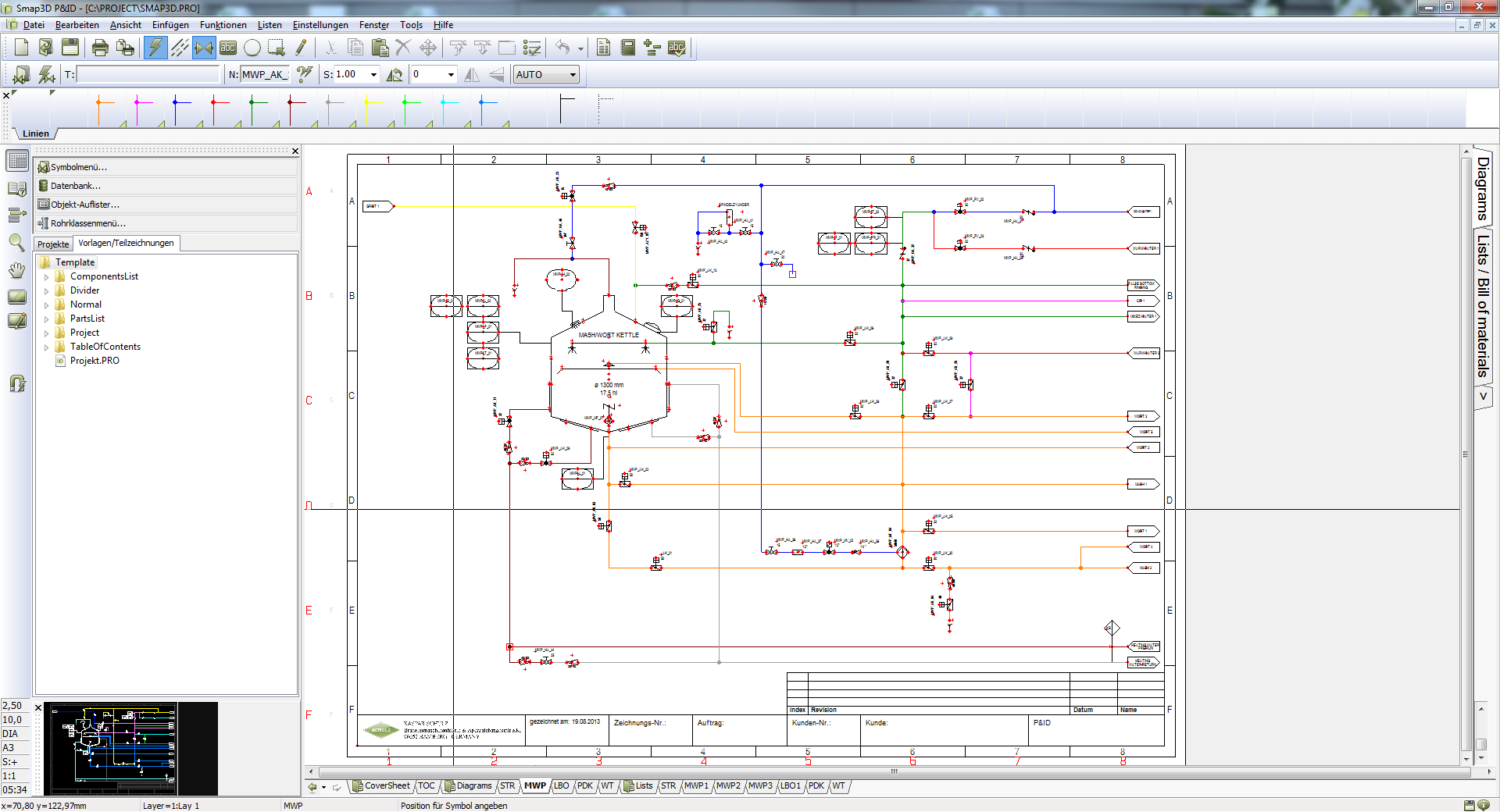
The initial pipeline layout can be defined using 2D flow diagrams that are easily created using an extensive icon library. The icons are linked to database elements that the designer then places in the piping module in accordance with a task list. Differences between the P&ID diagram and Excel parts list are thus a thing of the past.
 Creating a 2D P&ID diagram using Smap3D is a critical first step in process plant design
With the piping module from Smap3D Plant Design integrated in Solid Edge, the potential for errors significantly drops and design productivity increases. The designer selects from a library of standard piping sizes and corresponding fittings. Until recently, this took place using 2D drawings and lists of components stored in Excel files. Now Smap3D Piping design and component selection is fully integrated into the 3D design process. “The modifications due to errors that are not detected until production have decreased tremendously,” says Montag. In addition, the Smap3D database elements are linked to item records in ERP systems. As a result, designers are saved from doing the same work twice to create parts lists. “The integrated solution for pipe routing has made us up to three times faster in comparison to the earlier procedure,” says Montag.
You can read the full Kaspar Schulz case study here.


Comments