Using short fiber reinforced composite materials? Streamline structural simulation modeling
Why short fiber reinforced composite materials?
To increase energy efficiency and reduce harmful emissions, manufacturers work hard to reduce weight of components used in vehicles and machinery. However, reducing weight also impacts the structural integrity of a component. So materials engineering plays a big part in helping manufacturers develop lighter parts and products without compromising on structural performance.
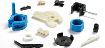
The use of short fiber reinforced composite materials (SFRP) contributes to this objective. SFRC is an attractive material for industrial applications because these materials are easy to manufacture and provide favorable performance properties at low weight. Great – problem solved, right?
Not exactly.
What are the SFRC material properties?
When developing a new product, engineers need to predict how a product will perform before they begin production. Physical testing of prototypes is one way to verify performance, but that takes too long and is too costly. Most companies use some form of simulation today, but predicting performance of parts and products made from SFRC materials is much more challenging than predicting the performance of uniform, isotropic materials. The reason is because the injection molding process used to manufacture SFRC parts affects how the short fibers are oriented within the component. These fibers will have different orientations in different areas of the part depending on how the material flowed into the part. This gives the part non-uniform, inhomogeneous material properties. Which means different areas of your part will react to loading conditions differently. How does an engineer predict how the component will perform if the material properties are unknown?
Finding fiber orientations
Luckily imaging techniques, like CT scanning, and software tools for injection molding simulation exist. Engineers can leverage these tools to determine the fiber orientations in an SFRC part. But knowing the fiber orientations only gets you part of the way. The tricky and time-consuming part of the process is applying this to your finite element (FE) model.
Typically, this has consisted of three tedious, manual steps:
- Mapping of fiber orientation results to a differently refined structural mesh
- Decomposition of fiber orientation tensors to principle directions and degree of alignments
- Creation and assignment of microstructural models to appropriate element regions
Simcenter 3D automates SFRC microstructural modeling
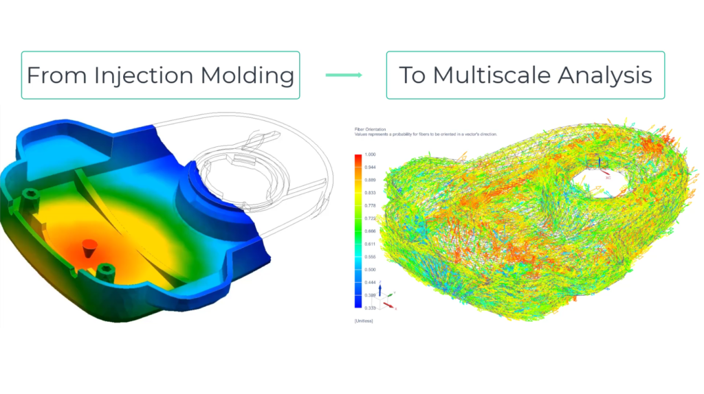
Simcenter 3D now has the ability to automate and streamline the complex task of creating and simulating an adaptive multiscale model of an injection molded SFRC component. This injection molding multiscale workflow works by connecting injection molding simulation results with a structural solver. The solution works in connection with different injection molding simulation tools as well as with structural finite element solvers from Simcenter 3D or third-parties via the Simcenter 3D Materials Engineering.
An example workflow would be something like this:
- Create a parameterized part that meets design criteria in your CAD system of choice
- Run an injection molding simulation in any injection molding simulation tool
- Import the injection molded results into Simcenter 3D
Simcenter 3D automatically maps the injection molding simulation results of fiber orientations to your structural mesh and creates microstructures to fit those fiber orientations.
Now you’re ready to simulate and evaluate the performance of your SFRC component using multiscale analysis. Because Simcenter 3D automatically created the microstructures, you can focus your efforts on the constituent material properties in order to achieve higher accuracy than with analytical methods.
Furthermore, since the constituent materials are the only materials needed for this analysis, the multiscale methodology returns valid results when changing processing parameters and material specifications. For example, if you have a database of properties for a wide range of thermoplastics and fibers (carbon, S2, etc), then you can much more easily explore multiple resin-fiber combinations.