Using 3DSync for Geometry Simplification and Edits
 I usually write for CAD users, so writing for folks who lean more toward the analyst side and who consider CAD to be a secondary skill is a bit new but bear with me. I’m at least still writing about CAD
The tools found in 3DSync are ideal for the needs of analysts working with imported models. In this article we will take a detailed look at three functions that should make your life easier if you are doing simulation work: Removing fillets, edits with the steering wheel, and dimensions.
The part shown to the right is provided at the bottom of this article in start and finish states as a downloadable attachment if you want to follow along with some of the steps given toward the end of this article. If you don’t have 3DSync or Solid Edge installed on your computer, you can get a free 45 day trial license from this link.
 These techniques are good whether the part is a native Solid Edge part, or if it came from an import. One of the first things you might want to do when you work on a part like this is to remove all the fillets. To get started, click on the Tools tab, and select the Simplify model option on the left side of the ribbon interface. The simplified model is typically used for simulation and to reduce overhead for large assemblies.
Delete Faces
Next, click back on the Home tab, and in the Modify group, click the dropdown arrow for Delete, and select Faces. You can also use the Delete Rounds tool, but in this particular case, the Delete  Faces works better. If you want to experiment with this on your own, try the Delete Rounds tool. Every part will be different, and the complexity of overlapping round faces is usually the determining factor as to whether the easiest method will work 100% or not.
You can delete all the rounds from this part with 3 Delete Face operations.
- Press ESC twice to clear any pending command
- On the Home tab, the Modify group, click the drop down arrow for Delete and select Faces.
- Set the Select option in the Command Bar to Feature.
- Select the rounds at the two places indicated by the image below on the left, and press Enter.
- Click Finish
- Select the round face indicated in the middle, then press Enter
- Click Finish
- Select the round face indicated on the right, then press Enter

When you are done, the Pathfinder should look like the image to the right, and the clevis part should have all sharp edges.
 Using the Steering Wheel
The Steering Wheel is the interface control that enables you to move and copy geometry in Solid Edge. The arrows of course enable you to move in a specific direction, and the torus enables you to revolve or tilt something about an axis. The flat blue  washer enables you to move items on a plane. Whenever you select a face on a Solid Edge model, you get a single arrow which is perpendicular to the selected face. This enables you to move that face along the arrow. To get more options to move, pick on the blue ball at the origin of the Steering Wheel.
The Steering Wheel only appears when you are in Synchronous mode. It will not show up if your part is in Ordered mode.
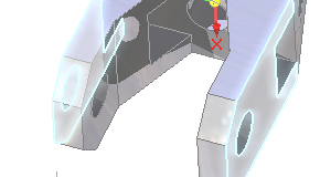
- Press ESC to clear all commands
- Click on face shown in image to the right
- Click on arrow perpendicular to face

- Move it in and out to see how it affects the part
- Key in a number that represents the change in mm, 20mm should work.
So that’s one way that you can use the steering wheel. The Live Rules panel that shows up at the bottom is more advanced stuff, and we’ll visit that in a later article.
Another way you can make changes is with dimensions.
- On the Home tab, Dimension group, click on the Smart Dimension tool.
- Reposition the part (drag middle mouse button) so you can see the end shown to the right.
- Click on the two outer edges to create the 60mm dimension shown
- Make sure to click the center arrow button so that the dimension changes symmetrically instead of to one side.
- With the dimension dialog still open, scroll the value with your mouse wheel, and watch
 the part update in width.
 - Also, click on the Lock icon so that it looks locked (in the image to the right it is not locked). This will make this dimension a driving dimension, so that it cannot be changed automatically.
Summary
Delete Face, Steering Wheel and Dimensions are great ways to alter imported parts in 3DSync, making it a very powerful tool for pre-processing geometry and preparing it for simulation.


