What’s new in Simcenter FLOEFD 2412? | CAD-embedded CFD simulation
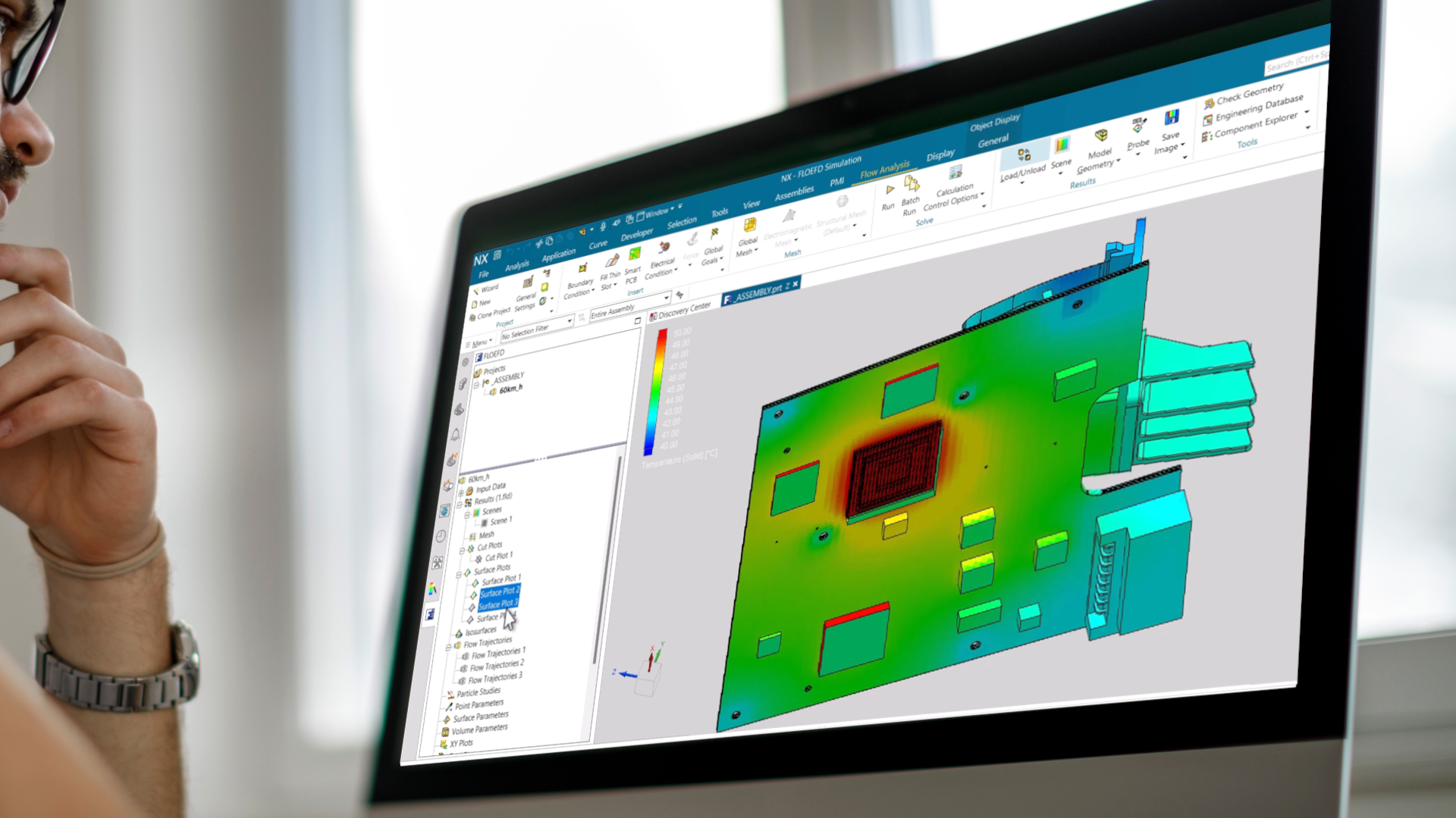
The new Simcenter FLOEFD 2412 software release is now available in all its CAD-embedded CFD versions, and Simcenter 3D embedded version. This release delivers electronics applications enhancements for PCB thermal analysis workflows. For example, in the area of processing imported EDA data and component placement, there are new ways to add libraries and quicker methods to swap thermal models of components within the EDA Bridge utility. Users are also able to more easily create of 2-resistor and LED component thermal models directly in the interface. Learn more about improved handling of missing material for thin gaps in complex CAD assemblies and read on below to discover many other topics such as examples for simulation automation, new plots and goals location functionality, and even batch simulation processing capabilities.
For NX users – You can also learn about the newly released NX CFD Designer, a new accessible native NX simulation tool, powered by Simcenter FLOEFD technology, that supports designers with a subset of common fluid flow and thermal analysis capabilities.
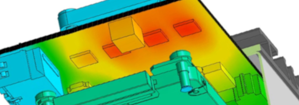
Model the complexity

PCB thermal analysis enhancements

EDA Bridge: Libraries and swapping PCB component thermal models
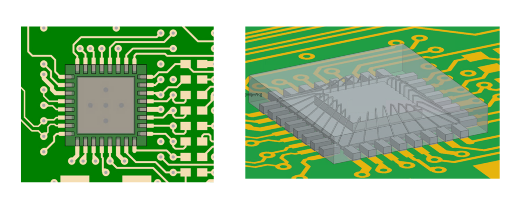
Positioning and replacing component models with IC package thermal models of suitable fidelity as part of the process of EDA data import into the electronics cooling tool environment can be a manually time-consuming task. In response to a popular user request, in Simcenter FLOEFD 2412, there are enhancements to the EDA Bridge utility so that that you can more easily replace components with thermal models contained within an existing library source.

Libraries – adding sources
Users can add libraries of component sources from either local files, mapped network locations or multiple locations. This way you can leverage your organizations component libraries as you expand them, or if you are importing component libraries from Simcenter Flotherm XT.
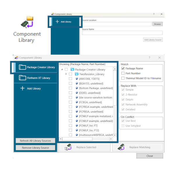
You add sources from within the component library in EDA Bridge. This operation does not modify the location files of the sources and you can remove library sources without impacting the files where they are located. You can also refresh sources so they are up to date when in the Component Library window.
Replacing components in EDA Bridge – new methods
You now have the following replacement options from within EDA Bridge:
1) Replace automatically (Replace Matching)
- Matched by Package Name, Part Number or Thermal Model ID
- Specify model level type to use
2) Replace manually (Replace Selected single or multiple components)
There is also scripting based support for the above replacement operations so that you can leverage these new capabilities in your automated workflows.
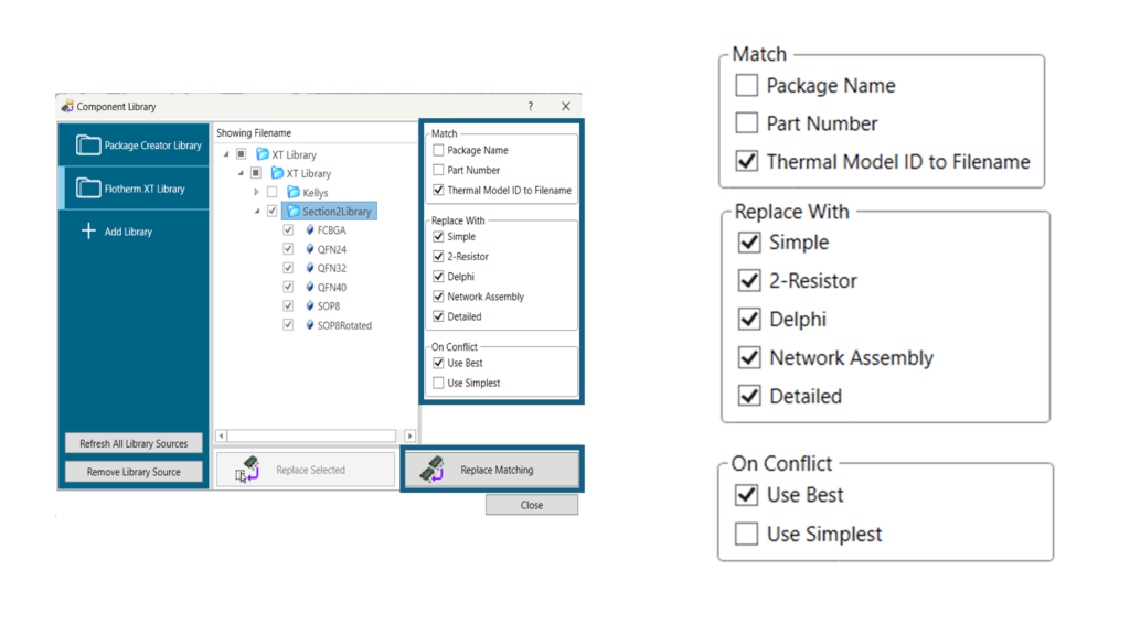
Watch the short illustrative video below. A workflow is shown starting from a detailed thermal model being added from Package Creator utility as a source into a library and then the steps within EDA Bridge are shown for replacing a selected simple component using the “replace matching” option. The model is then PCB and replaced component are then transferred from EDA Bridge to Simcenter FLOEFD for NX.
Additional new option awareness: When transferring from EDA Bridge to Simcenter FLOEFD, you can now select to import components from EDA bridge as parts or bodies, depending on your preference. You can therefore specify if you want a single multi-body part or an assembly of parts based on your preference.
Component Explorer: 2R thermal and LED component model creation
When you have a board level model with a high number of components and you want to create and edit the component thermal representations, this can be time consuming and there is also potential for errors in a repeated manual entry approach to this task. You can now specify LED or 2R components using Component Explorer directly in Simcenter FLOEFD 2412 quickly and also leverage Excel import of tabular feature data.
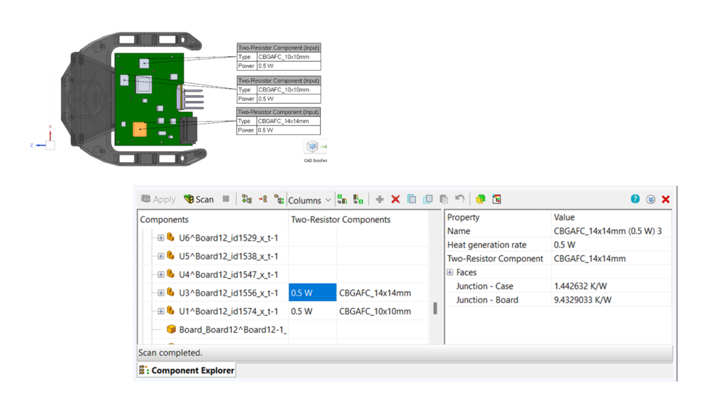
2R models procedure
- Specify the power in the 2-resistor column
- Select the component type
Or for a list of components you can fill in the Component List Excel spreadsheet with 2 resistor parameters and then import it into component explorer to create all features instantly.
This is illustrated in the following video:

How to export all component temperatures quickly – a reminder on using the Heat Flux Plot
While on the topic navigating and selecting multiple components, a reminder for users that you can use the heat flux plot to select multiple components or all components and then export in tabular format to Excel component temperatures. Learn how in this video below. It starts from a solved model looking at surface temperatures and flux plots enabled and shows the steps to export component temperatures:

LEDs : specifying features individually or for multiple models
The following video shows the selection of all LED components in Component Explorer and then either editing amp value and LED type directly for selected LEDs or importing a table of updated information via Excel spreadsheet.

Component Explorer: Surface source power listing and summation
It is advantageous in thermal management studies to have a clear way to see different sources power across a board and to consider overall power budget contributions. Within component explorer a new column has been added to reflect surface source power.
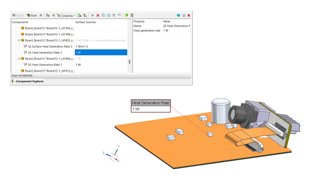
The following video compares viewing a single source vs viewing a group of sources in Component Explorer.

Smart PCB and Simcenter FLOEFD API Automation: SVG export/import
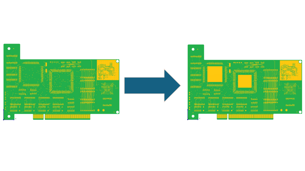
To aid automation of script driven, automated what if analysis by leveraging the Simcenter FLOEFD API, it was identified by users as advantageous to be able to modify copper regions on a Smart PCB after it is imported into Simcenter FLOEFD 2412. To support this, functions have been added to the API to export and import a Smart PCB to and from a set of SVG files.
Export, creation script commands and SVG tags so you can fill areas with copper are detailed in documentation on Support Center for users.

Material handling in CFD simulation of small gaps in assemblies: Fill Thin Slots feature
Thin gaps are often in CAD assemblies. For example, these may be between heated components and heatsinks on a PCB or they are gaps between glued parts may exist in models. These gaps are meant to be filled with Thermal Interface Materials (TIMs) or glue during assembly procedure. For simulation models with unfilled gaps, their presence may impact thermal results.
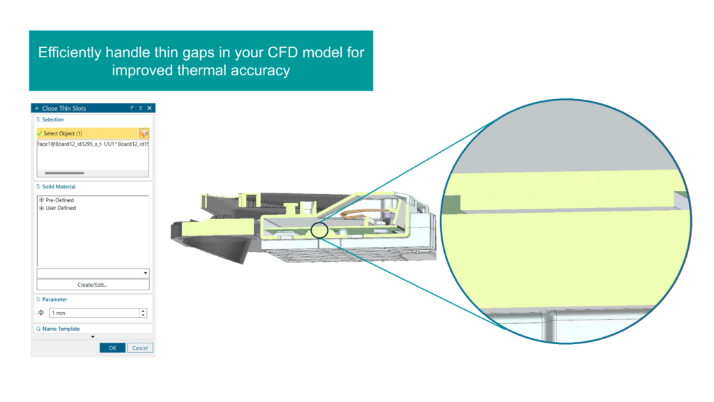
In Simcenter FLOEFD 2412, you can opt to fill mesh cells inside a gap with specific solid material automatically in accordance with thickness criteria value. This is faster than creating specific geometry parts in the CAD model to fill the gap. The mesh and shape created is viewable with postprocessing tools stage. The following video illustrates the steps involved to leverage this new feature.

Structural analysis: 2nd order elements
This release introduces 2nd order elements to reduce reliance on overmeshing for some models to maintain accuracy e.g models such as thin plates with significant temperature gradients across them as a temperature load. This is selected in calculation control and setting the Nastran element type to 2nd order.
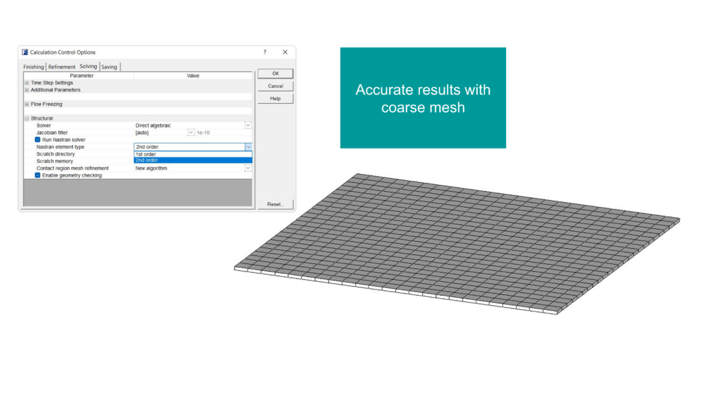
2nd order elements enable you to leverage a more Coarse mesh while approaching close accuracy to within an order of magnitude of a fine mesh 1st order solution.

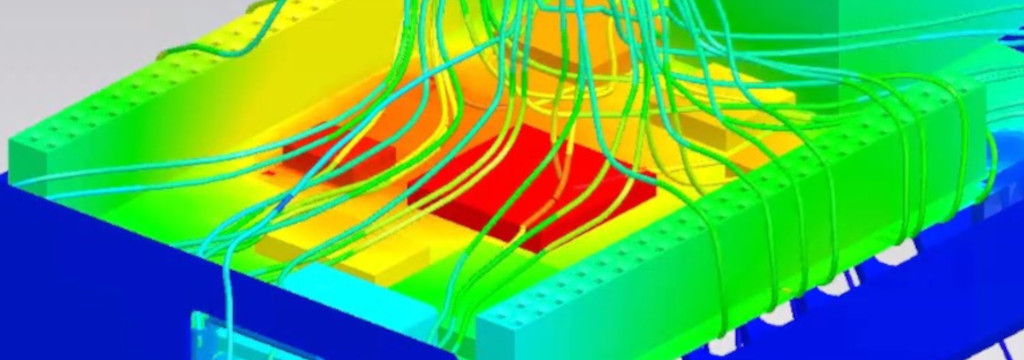
Go Faster

Minimum and maximum goals locations
It is useful to have coordinates of minimum or maximum parameter points in a simulation model when exploring the design space or operational scenarios. Equally valuable are specifying coordinates for a specific objective function in a parametric study.
You can now designate a point of volume or a surface goal within the Equation Expression field. Functions to locate a point of volume or surface goal are available in Equation Goal expression are written in the following ways:
- GoalLocationX({Goal Name})
- GoalLocationY({Goal Name})
- GoalLocationZ({Goal Name})
Where Goal Name is the name of minimum or maximum surface or volume goal. In the following video you can observe the set up.
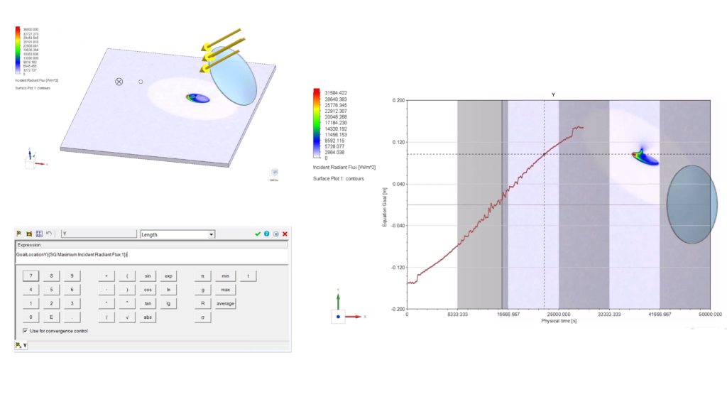
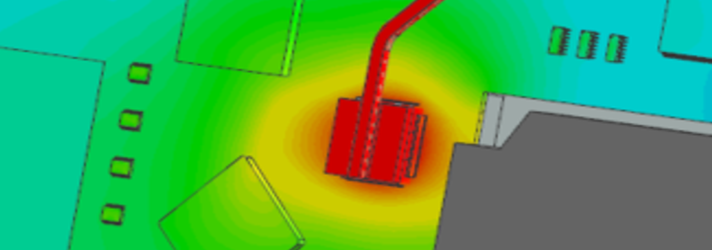
In this simple demonstration video below there is a lens and the aim is to leverage radiation modeling in a transient study around the source movement to look at the hotspot intensity and position created on a surface. The goal is to track the hotspot movement across the surface using a plot of position of the maximum value of radiation flux.

Exploring results: Bubble chart for parametric studies
You can now compare design points of resulting parametric study for multi-parameter optimization using a bubble plot. This means you can evaluate up to 4 parameters in this clear way on one chart.
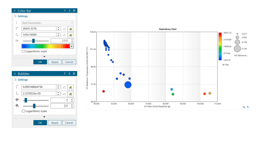

Simulation automation: new examples for the Simcenter FLOEFD API
The new Simcenter FLOEFD API was introduced in version 2312, with Python support added in version 2406. In latest Simcenter FLOEFD 2412 release new examples and enhancements have been added. You can now find the following examples:
- Porous Media
- Equation Goal
- Smart PCB Export/Import
- Radiation Surface and sources
- LED and Two Resistor examples
- Solid Material
You can also find out about controlling number of cores for a calculation, importing power maps, setting subdomains and a whole list of other enhancements. Information on these scripting commands and enhancements is located in the help reference and support center supporting document.

Explore the possibilities

Batch results processing for intermediate results
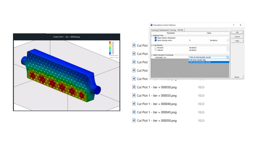
If you are using any command line driven operations for batch analysis or server based batch analysis and you want to export intermediate graphical and Excel based results data, then please note you can do this as of Simcenter FLOEFD 2412. This has advantages for tracking parameter fields during a simulation run on the server side and avoids processing and time overheads of copying huge data binary files frequently back locally.


Stay Integrated

Introducing NX CFD Designer

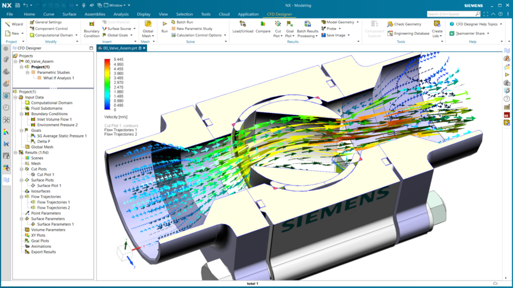
Siemens Digital Industries Software supports clients in the creation of a digital twin of their product and also promotes flexible open ecosystems for streamlined development by providing tools to suit the wide variety of engineering user personas and applications. In a move to further democratize CAE tool use and to foster earlier and wider use of CFD simulation in particular, NX CFD Designer has been introduced as of December 2024.
NX CFD Designer is a new accessible CFD simulation tool specifically for designers working in NX that empowers earlier decision making. Designers access a set of common fundamental fluid flow and thermal simulation capabilities without leaving NX. Results are viewed on parts geometry and assemblies directly and you can explore performance of different design options. NX CFD Designer features guided simulation set up, automatic meshing, a unique solver technology from Simcenter FLOEFD, and easy results post processing and viewing options provide simulation driven insights for design improvement.
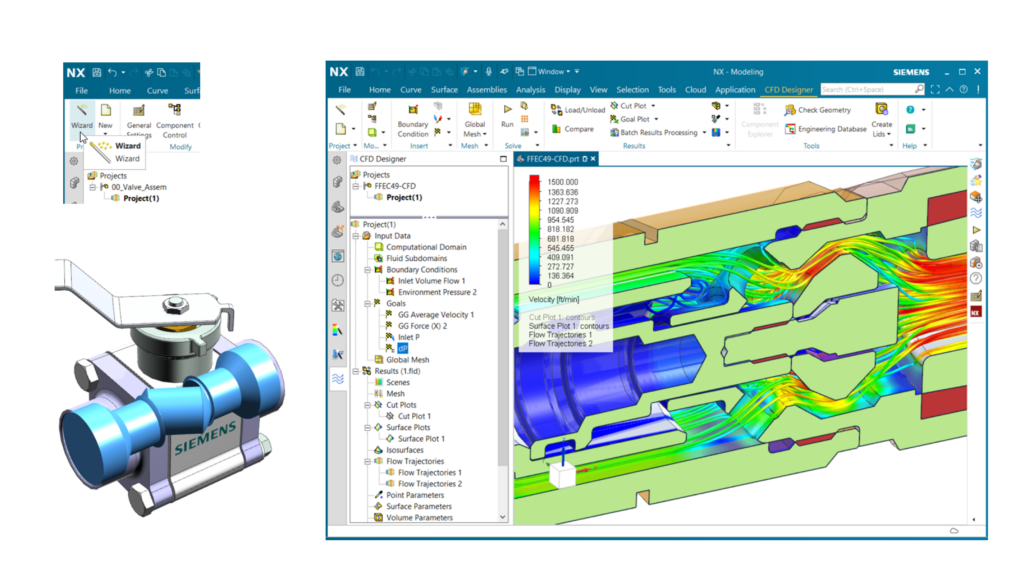
NX CFD Designer is included within the NX installation kit and is accessible through NX Value Based Licensing. It is based on Simcenter FLOEFD technology so as a design requires more advanced analysis types at any point, such as transient simulation, then models are fully transferable to Simcenter FLOEFD for NX for further study.
NX users can learn more about the full December NX 2412 release in this article by the NX team. Please stay tuned in coming weeks and months for more information and new video tutorials for NX users on how to apply NX CFD Designer in your process.

——————————————————————————————————————————————
Where to download Simcenter FLOEFD 2412:
Users can download all variants on Support Center via the following links:
