Reduce model complexity with Simcenter Reduced Order Modeling

Models are the core of all model-based techniques for design, control, optimization, simulation, etc. Detailed models are the core of design activities and can be complex and slow to compute. How to make simplified, multi-purpose versions for scaling and deploying their usage? The answer is Reduced Order Models (ROMs).
ROMs are an efficient way to reduce the complexity of models and extend their application range. They are key components for several applications like integrating 3D models into 1D ones, speeding up simulations, enabling digital twins and real-time applications, creating virtual sensors, and protecting IP (Intellectual Property).
Today’s application will show how to reduce electric power systems using Simcenter Reduced Order Modeling. The system depicted in Figure 1 represents a transmission system in which the generated power (represented here by input voltage source) is amplified by the transformer and transmitted to the load (battery pack) through the transmission line.
Here, the complexity comes from the transmission line model. Basically, to well capture transient phenomena, the transmission line model is discretized over space where each section (here 50 sections for 100 Km) is represented by a simple circuit, as shown in Figure 1. When the number of sections increases, the model will be more accurate, but the number of state variables will increase. This makes the whole model quite large and memory-consuming.
In that context, the objective behind making a ROM is to:
- Reduce the total number of state variables by simplifying the model of the transmission part (transformer + transmission line)
- Reproduce faithfully the transient phenomena resulting from the different interconnexions
This will be done using Simcenter Reduced Order Modeling.
The tool offers various ways to make ROMs: either from simulation data by using, e.g., Neural Networks and Response Surface Models (RSM) techniques or models like state-space matrices of a linearized model like in our application here.
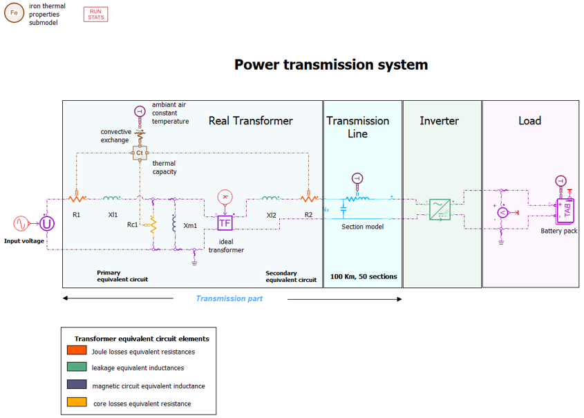
Figure 1
The whole process can be summarized in few steps:
- Isolate the transmission part
- Use Simcenter Reduced Order Modeling to make a ROM
- Connect the ROM to the rest of the system
- Check results accuracy
Let’s get started.
Step 1:
Before making a ROM, the transmission part is disconnected from the rest of the system as depicted in Figure 2 and linearized using Simcenter Amesim. The input variables are the input voltage of the transformer as well as the voltages at the transmission line extremity. A choice was made to consider the voltages at the connection points as inputs and currents as outputs. This helps to make a physical connection between the ROM and the rest of the physical model.
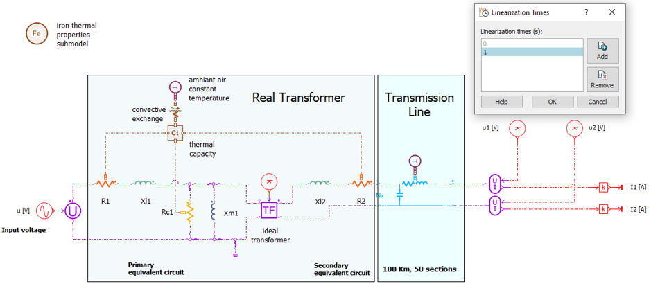
Figure 2
That’s all for the first step, and we are ready to start making a ROM.
Step 2:
The second step consists of loading the linearization data (matrices) into Simcenter Reduced Order Modeling, computing a reduced model, evaluating it, and exporting it. Let’s see how it works.
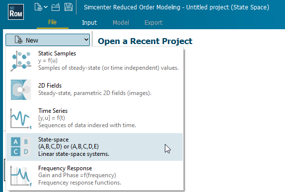
The first step is to open Simcenter Reduced Order Modeling and to create a state-space project as depicted below.
Next, load the linearized model created before using Add data button. By selecting the Simcenter Amesim model of the transmission part, all the computed linearized models are proposed. Let’s pick the one computed at 1 second.
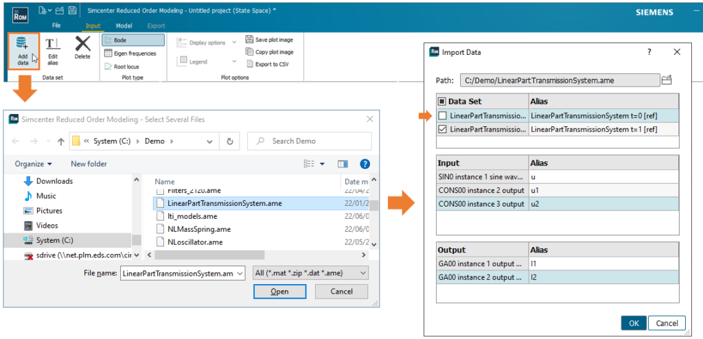
Figure 5 shows the properties of the loaded model.
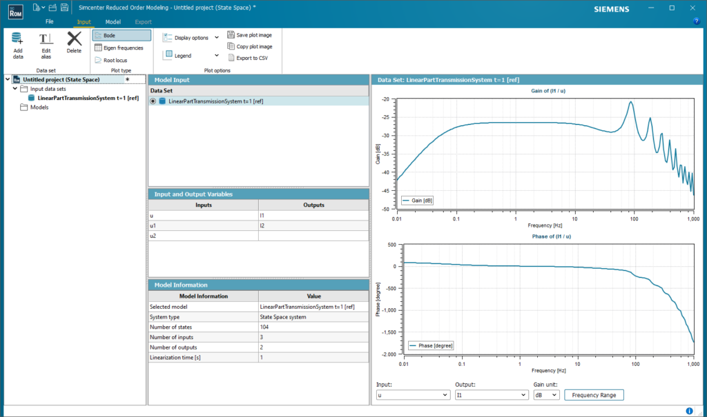
Figure 5
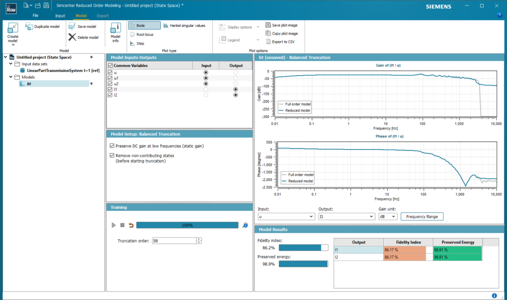
Now, let’s move on to the model tab and make a ROM. By clicking on the New model button, different model types are proposed. Here, we are dealing with a medium-size model having 104 state variables. In such a case, the Balanced Truncation is a good candidate.
When clicking on the start button, a ROM is computed and evaluated automatically. A truncation order of 58 is proposed here based on the Hankel singular values of the model. The tool indicates an overall fidelity index of 86 %. By looking at the frequency response plot, one can see that the ROM covers a large frequency bandwidth (up to 2.6 kHz) of the original model, which is good enough for our application.
The next step is to save the computed model using Add model feature as depicted below.
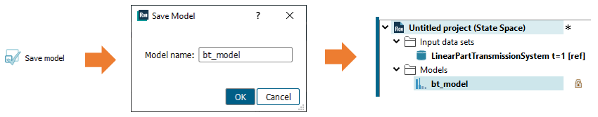
The computed model being saved, let’s go to the Export tab and export it.
Step 3
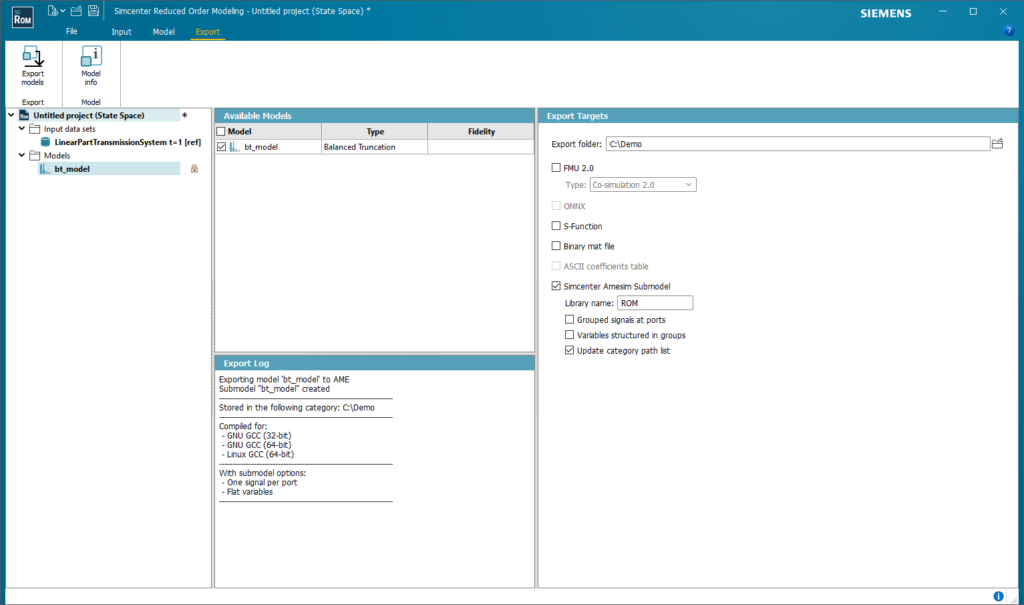
To tackle various applications, four targets are proposed when exporting state-space ROMs. They allow connection with both Simcenter Amesim and other simulation tools using, e.g., FMUs (Functional Mock-up Units) for co-simulation or binary files.
Here, the computed ROM is exported as a Simcenter Amesim submodel.
Back to Simcenter Amesim, let’s now connect the exported ROM (available in the ROM library specified at the export stage) to the rest of the power system, as depicted in Figure 9. Two first-order lags with a cut-off frequency of 2.5 kHz are added to keep signals within the frequency range of interest (up to 2.6 kHz). Our reduced power system now has 62 state variables compared to 106 for the full power system depicted in Figure 1. The full size of the original model is then reduced by 41.5 %.
Almost done! All to do now is to validate the ROM by comparing the full (Figure 1) simulation results and reduced (Figure 9) power system models.
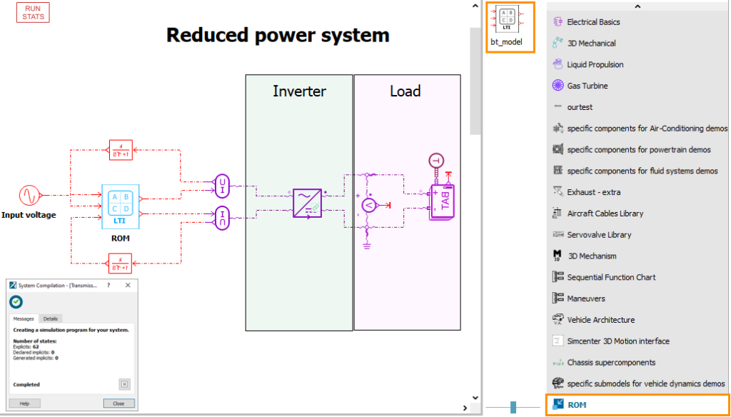
Figure 9
Step 4
Both power systems depicted in Figures 1 and 10 are simulated for 2 s with a variable step solver using Simcenter Amesim.
Figure 10 shows the input voltage of the battery as well as its state of charge.
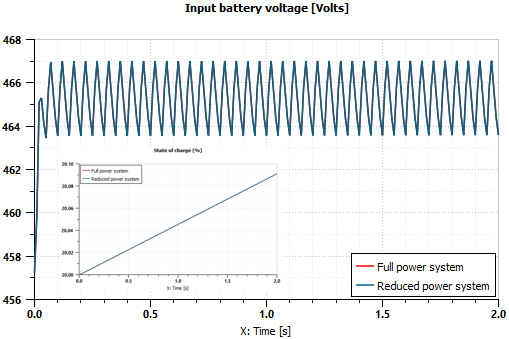
Figure 10
The results show a high quality of fit with fewer state variables (62 compared to 106). This is reflected by the fidelity metrics (overall fidelity of 86 %) indicated by Simcenter Reduced Order Modeling. In terms of usability, the obtained ROM can be used as a digital twin of the transmission part. It can also be shared between different partners working on the same application and possibly using different simulation tools.
Conclusion
It was shown here how to reduce electric power systems using Simcenter Reduced Order Modeling. It allows you to easily minimize the number of state variables of a power system by making a ROM of its transmission part. This has many advantages:
- It extends the scope of the model by making it less memory consuming
- It allows sharing models with different partners while preserving the IP
- It enables fast prototyping and design
For that, Simcenter Reduced Order Modeling offers nice features to easily make a ROM for a state-space model of large-scale. The workflow is simple and intuitive, with the possibility to easily assess the fidelity of the ROM based on different fidelity indicators. The tool also offers different export targets to address all possible usage so that the computed ROM can be used in different contexts.
About the author:
Mohamed Belhocine – After a Ph.D. in simulation and controls of large electrical networks, Mohamed developed control strategies for electrical systems and aircraft controls before joining Siemens as a control expert. He is part of the Control group, which takes care of control, identification, and model reduction topics for Simcenter Amesim.
Learn more


Comments
Comments are closed.
Thank you for great exposition of the capabilities Mohamed, I was wondering are there similar examples on the mechanical side? For example, system level model wave form replication of a vehicle durability simulator, where one can model the simulator and a vehicle in a closed loop? Or a simpler case of fitting a very coarse finite element mode (for a vehicle and its suspension, beams, springs, lumped masses and dampers) parameters to data.
Thanks!